
Ignition/injection system control unit mount - r r
- Make
- Alfa Romeo
- Model
- GT Factory Service Manual
- Year
- 2003–2010
- Section
- Petrol injection system › Ignition/injection system control unit mount - r r
IGNITION/INJECTION SYSTEM CONTROL UNIT MOUNT - R R
Removing
Make sure that the ignition key is in the OFF position, then disconnect the battery terminal (-).
| Description | Connector | |
|---|---|---|
| Battery | A1B |
1. Disconnect the electrical connections (1a) and (1b) from the injection/ignition control unit.
| Description | Connector | |
|---|---|---|
| 1a | Engine management control unit | M10A |
| Description | Connector | |
|---|---|---|
| 1b | Engine management control unit | M10B |
2. Release the electrical wiring from the fastening on the injection/ignition system control unit mounting.
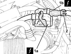
Proceed with the removal
Op. 1048A34 SLEEVE(S) FROM FLOW METER TO AIR SUPPLY CAPACITY CASE - R + R.
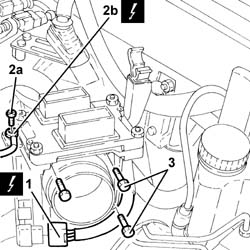
1. Disconnect the electrical connection from the throttle casing integrated with D.V.L. and release the wiring from the band on the mounting.
| Description | Connector | |
|---|---|---|
| 1 | Throttle body actuator | N75 |
2. Undo the bolt (2a) and disconnect the earth lead (2b) from the injection/ignition control unit mounting.
| Description | Connector | |
|---|---|---|
| 2b | Earth on engine | C40C |
3. Undo the bolts fixing the injection/ignition system control unit mounting.
The above bolts also secure the throttle casing integrated with D.V.L. to the modular intake manifold.
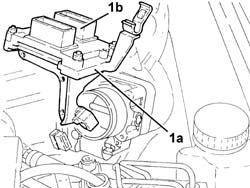
1. Remove the injection/ignition system control unit mounting (1a) complete with control unit (1b).
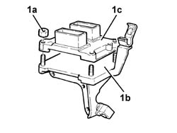
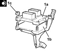
1. At the bench, undo the nuts (1a) and separate the injection/ignition system control unit mounting (1b) from the control unit (1c).
Refitting
1. At the bench, assemble the control unit (1a) on the injection/ignition system control unit mounting (1b) and fasten it tightening the nuts (1c) to the recommended torque.
| Fastening | Component | Ø | Value (daNm) | |
|---|---|---|---|---|
| 1c | Nut | INJECTION/IGNITION SYSTEM E.C.U. | M6 | (Mount side) 0.8 - 1.1 |
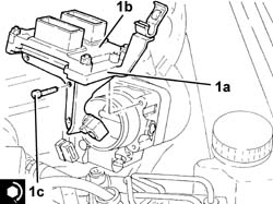
1. Refit the injection/ignition system control unit mounting (1) complete with control unit (1b) back in its housing and secure it tightening the bolts (1c) to the recommended torque.
The above bolts also secure the throttle casing integrated with D.V.L. to the modular intake manifold.
| Fastening | Component | Ø | Value (daNm) | |
|---|---|---|---|---|
| 1c | Bolt | BUTTERFLY VALVE CASE/S (MPI) | M6 | (Air chamber side) 0.8 - 1.1 |
Connect the earth lead to the injection/ignition control unit mounting and secure it using the bolt.
Connect the electrical connection to the throttle casing integrated with D.V.L. and fasten the wiring to the band on the mounting.
Proceed with the refitting
Op. 1048A34 SLEEVE(S) FROM FLOW METER TO AIR SUPPLY CAPACITY CASE - R + R.
Connect the electrical connections to the injection/ignition control unit and fasten the electrical wiring to the injection/ignition system control unit mounting.
Connect the negative battery terminal (-).
Parts & tools for this job For 2003 Alfa Romeo GT
- PARTEngine gasket setSearch: Alfa Romeo GT 2003 engine gasket set
- TOOLTorque wrenchSearch: 3/8 inch torque wrench
- TOOLFeeler gauge setSearch: feeler gauge set
Links open Amazon search results in a new tab. As an Amazon Associate I earn from qualifying purchases.