
Inlet / Exhaust Manifolds
- Make
- Aston Martin
- Model
- DB9 Factory Workshop Manual
- Year
- Issue 2, 2005
- Section
- Engine Structure › Inlet / Exhaust Manifolds
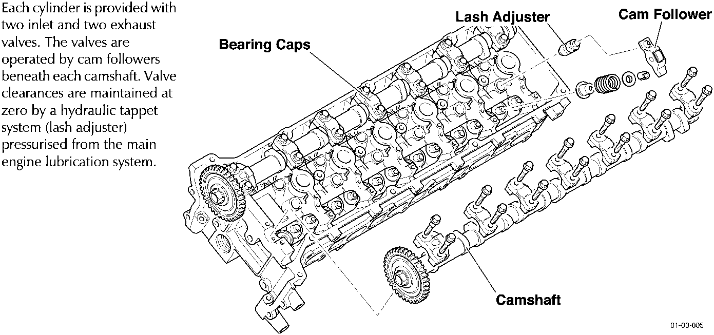
Each cylinder is provided with two inlet and two exhaust valves. The valves are operated by cam followers beneath each camshaft. Valve clearances are maintained at zero by a hydraulic tappet system (lash adjuster) pressurised from the main engine lubrication system.
Inlet / Exhaust Manifolds
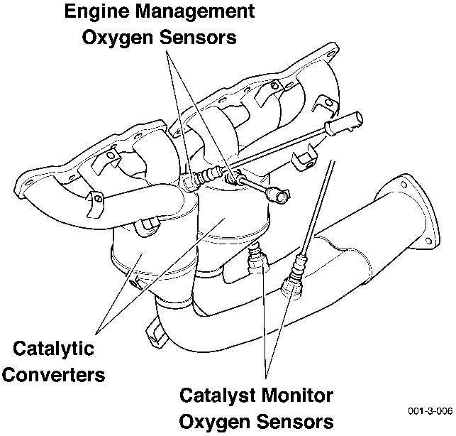
Two six-branch exhaust manifolds, locate four primary catalytic converters and eight oxygen sensors.
Four engine management oxygen sensors are mounted before the primary catalysts. Four catalyst monitor oxygen sensors are mounted after the primary catalysts.
Intake air is filtered and passed through mass air flow meters (MAF). The air then passes through the throttle bodies into the six branch inlet manifolds.
Specifications
| Block | MM | ||
|---|---|---|---|
| Cylinder Bore Grade 2 | 89.010 - 89.020 | ||
| Main Bearing Bore (without shells) | 72.400 - 72.424 | ||
| Cylinder Heads | MM | ||
|---|---|---|---|
| Head Face-Roof Button | 14.75 - 15.25 | ||
| Valve Seat Width - Inlet | 1.10 - 1.40 | ||
| Valve Seat Width - Exhaust | 1.40 - 1.70 | ||
| Camshaft Bore | 26.987 - 27.012 | ||
| Camshaft Journals | 26.936 - 26. 962 | ||
| Head Volume | 46.70 - 49.70 ml. | ||
Camshaft End Play
0.025 - 0.165 mm (using a force of 30-50 lbs - do not exceed 50 lb. as damage may occur to the thrust washer).
| Camshaft Sensors | MM | ||
|---|---|---|---|
| Air Gap | 1 (±0.5) | ||
Torque Figures
| Description | Nm. | lb./ft. | |
|---|---|---|---|
| Cylinder head | 1. Bolts 1 to 14 | 37-43 | 27.5-32 |
| 2. Bolts 15-16 | 15-20 | 11.5-15 | |
| 3. Bolts 1-14 | 85°-95° | ||
| 4. Release bolts 1-14 | Min. 360° | ||
| 5. Bolts 1 to 14 | 37-43 | 27.5-32 | |
| 6. Bolts 15-16 | 23-27 | 17-20 | |
| 7. Bolts 1 to 14 | 85°-95° | ||
| 8. Bolts 1 to 14 | 85°-95° | ||
| Camshaft bearing caps | 8-12 | 6-9 | |
Parts & tools for this job For 2005 Aston Martin DB9
- PARTExhaust gasketSearch: Aston Martin DB9 2005 exhaust gasket
- TOOLPenetrating oilSearch: penetrating oil
- TOOLOBD2 scannerSearch: OBD2 scanner
Links open Amazon search results in a new tab. As an Amazon Associate I earn from qualifying purchases.