
Component Checks (page 3 of 3)
- Make
- Aston Martin
- Model
- DB9 Factory Workshop Manual
- Year
- Issue 2, 2005
- Section
- Power Conversion
03 EngineComponent Checks · page 3 of 3
- Check the crankshaft turning torque.
The turing torque must not exceed 6 Nm. - Complete with their upper big end bearing shell, install the pistons and connecting rods in their numbered positions. If new pistons or connecting rods are being installed, check the piston height (Refer to 'Specifications', page 3-12-1).
Ensure that the piston rings are installed and located correctly (Refer to 'Pistons and Connecting Rods', page 3-12-1).
Arrows stamped on the piston upper surface must point towards the front of the engine during reassembly.
Use cylinder protectors during piston and connecting rod installation (Refer to '303-535 (Cylinder Bore Protectors)', page 20-1-4).
- Install the connecting rod bearing caps and shells, noting correct orientation of each cap.
Check that connecting rod and cap identification marks match and align.
Secure caps using two new bolts to each cap.
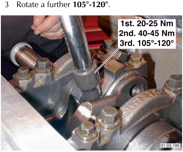
Torque all connecting rod bolts in three stages:- To 20-25 Nm.
- To 40-45 Nm.
- Rotate a further 105°-120°.
- Install the windage tray.
Torque nuts (x4) to 5-7 Nm + 45°. - Install new a 'O'-ring to the oil pick-up pipe.
Install the sump.
Ensure that the sump oil outlet locates to the oil pump inlet before the sump is faced up to the engine block.
Do not use a mallet etc. to face up the sump to engine block.
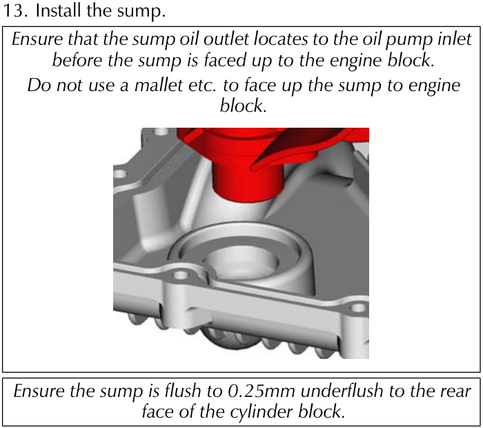
Ensure the sump is flush to 0.25mm underflush to the rear face of the cylinder block.
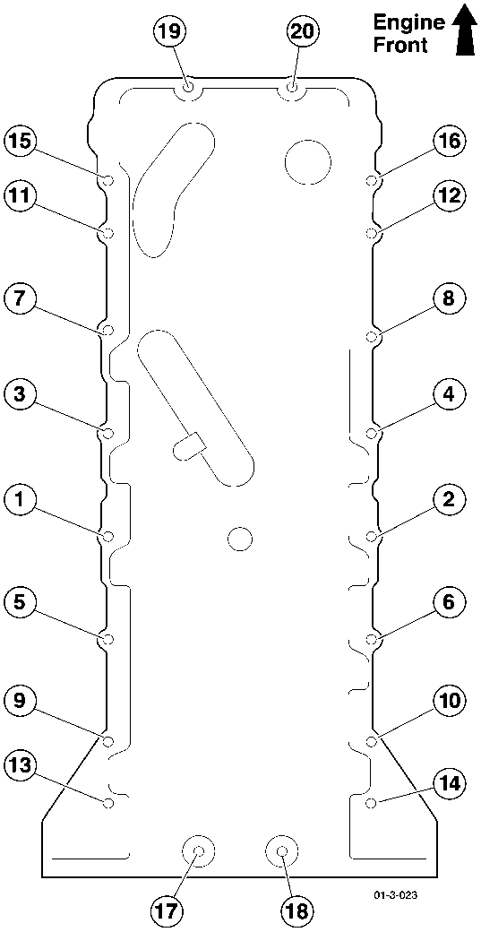
Secure the sump using bolts (x15 M8) and (x5 M6).Tighten the bolts using a two stage procedure:
- Tighten all bolts to 15 Nm. in the sequence shown.
- Tighten all bolts through a further 90° following the same sequence.
Parts & tools for this job For 2005 Aston Martin DB9
- PARTEngine gasket setSearch: Aston Martin DB9 2005 engine gasket set
- TOOLTorque wrenchSearch: 3/8 inch torque wrench
- TOOLFeeler gauge setSearch: feeler gauge set
Links open Amazon search results in a new tab. As an Amazon Associate I earn from qualifying purchases.