
Single cylinder head, removed - overhaul
- Make
- Fiat
- Model
- 500 Factory Service Manual
- Year
- 2007–2024
- Section
- Cylinder head/s › Single cylinder head, removed - overhaul
SINGLE CYLINDER HEAD, REMOVED - OVERHAUL
Removing
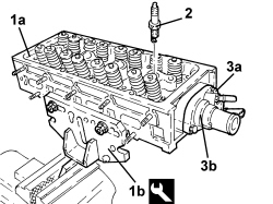
1. Position cylinder head (1a) in the vice supporting it using support tool (1b).
| Tool | Description | Function | Validity |
|---|---|---|---|
| 1.860.470.000 | Mount | Head overhaul | all versions |
2. Unscrew the spark plugs and remove them.
3. Undo bolts (3a) and remove thermostat (3b) complete with O-ring.
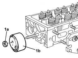
1. Undo nut (1a) and remove moving timing belt tensioner (1b).
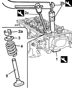
1. Fit the valve retaining tool beneath the cylinder head.
| Tool | Description | Function | Validity |
|---|---|---|---|
| 1.860.786.000 | Base | Valve retention | 1.4 16V |
2. Remove half-cones (2a) using tools (2b) and (2c).
| Tool | Description | Function | Validity |
|---|---|---|---|
| 1.860.644.000 | Lever | Dismantling valves | 1.4 16V |
| Tool | Description | Function | Validity |
|---|---|---|---|
| 1.870.890.000 | Chamber | Valve cotter removal | 1.2 8V 1.4 16V |
3. Fit the upper valve shims.
4. Remove the valve springs.
5. Remove the valves.
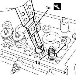
1. Use tool (1a) to remove oil seals (1b) from the valve guides.
| Tool | Description | Function | Validity |
|---|---|---|---|
| 1.870.894.000 | Calliper | Removing valve guide oil seals | 1.3 Mjet 1.4 16V |
2. Fit the lower valve shims.
- Remove the valve retaining tool and keep the valves.
- Loosen the vice, remove the cylinder head and place it on the bench.
- Remove the cylinder head support tool.
Op. 1016E14 VALVE GUIDES IN SINGLE CYLINDER HEAD - REPLACE DURING OP. 1016E10
Refitting
- De-carbonize and clean the valve seats and ducts.
- Clean any traces of the old gasket from the lower cylinder head surface.
- Check that the cylinder head plane flatness is within the recommended values.
| Measurement | Value | Validity |
|---|---|---|
| Cylinder head support surface flatness (mm) | < 0.1 | 1.2 8V 1.4 16V |
- If necessary, flatten the lower cylinder head surface; it is permitted to remove 0.1 mm of material from the minimum cylinder head height (factory value).
| Measurement | Value | Validity |
|---|---|---|
| Cylinder head height (factory value) (mm) | 77 ± 0.2 | 1.4 16V |
1. Check that the refacing has not changed any of the combustion chambers in the areas or else the head must be replaced.
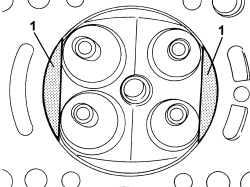
- Also check all the combustion chambers proceeding as follows:
1. Fit the valves and spark plugs provisionally. Take a graduated burette containing a known amount of engine oil.
2. Rest a glass plate on the cylinder head with holes corresponding to the combustion chambers.
3. Fill the combustion chamber completely, taking care not to pour oil outside the combustion chamber.
- Wait about 10 minutes to allow the oil to decant.
- Measure the amount of oil remaining in the burette and then calculate the difference between this and the amount of oil used initially with the burette full. The difference is the volume of the chamber.
- Check that this value is within specified values, otherwise replace the cylinder head.
| Measurement | Value | Validity |
|---|---|---|
| Combustion chamber volume (cc) | 14 | 1.4 16V |
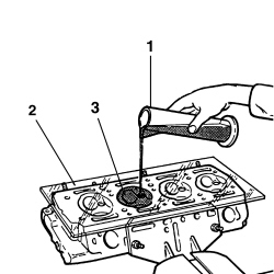
- Check that the valve stem does not show signs of grooves or seizing.
- Check that the diameter of the valve stems corresponds to the recommended figures; if not, replace the worn valves.
| Measurement | Value | Validity |
|---|---|---|
| Inlet valve stem diameter | 5.982 ÷ 6.000 | 1.4 16V |
| Measurement | Value | Validity |
|---|---|---|
| Exhaust valve stem diameter | 5.974 ÷ 5.992 | 1.4 16V |
- Check that the diameter of the mushroom valve corresponds to the recommended figures; if not, replace the valves.
| Measurement | Value | Validity |
|---|---|---|
| Inlet valve outer diameter | 27.020 ÷ 27.050 | 1.4 16V |
| Measurement | Value | Validity |
|---|---|---|
| Inlet valve inner diameter | 22.520 ÷ 22.550 | 1.4 16V |
- Check that the inner diameter of the valve guide and the clearance between it and the valve are within specified values, otherwise replace the valve guide.
- If necessary, replace the valve guides, refer to
Op. 1016E14 VALVE GUIDES IN SINGLE CYLINDER HEAD - REPLACE DURING OP. 1016E10
| Measurement | Value | Validity |
|---|---|---|
| Valve guide inner diameter (mm) | 6.022 ÷ 6.040 | 1.4 16V |
| Measurement | Value | Validity |
|---|---|---|
| Valve/valve guide clearance - intake (mm) | 0.022 ÷ 0.058 | 1.4 16V |
| Measurement | Value | Validity |
|---|---|---|
| Valve/valve guide clearance - exhaust (mm) | 0.030 ÷ 0.066 | 1.4 16V |
- Using special equipment, check that the valve spring specifications are within the recommended values; if this is not the case, replace the components that do not comply.
| Measurement | Value | Validity |
|---|---|---|
| Valve spring height released (mm) | 46.9 | 1.4 16V |
| Measurement | Value | Validity |
|---|---|---|
| Length of valve springs under a load of 14.9 - 16.5 daN (mm) | 37.52 | 1.4 16V |
| Measurement | Value | Validity |
|---|---|---|
| Length of valve springs under a load of 31.1 - 34.1 daN (mm) | 30.0 | 1.4 16V |
1. Fit lower valve shims (1a); place oil seals (1b) on the valve guides, positioning installing tool guide (1c) on the valve stem fitted provisionally in its seat, then fit a new oil seal on the installing tool.
2. Fit the oil seal in its housing using the fitting tool.
| Tool | Description | Function | Validity |
|---|---|---|---|
| 1.860.993.000 | Installing tool | Fitting valve guide oil sealing ring | 1.4 16V |
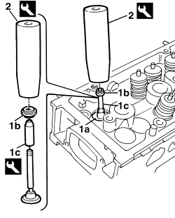
- Refit the valves, springs, upper plates and half-cones using the same equipment, as for the dismantling.
- Position the timing belt moving tensioner in its housing and secure it without tightening the nut.
- Place the thermostat in its housing with the new O-ring and secure it by tightening the bolts to the recommended torque.
| Component | Fastening | dia | Value (daNm) | Validity |
|---|---|---|---|---|
| Thermostat unit (on cylinder head) | Bolt | M6x1x22 | 1.0 | 1.4 16V |
- Fit the spark plugs and tighten them to the recommended torque.
| Component | Fastening | dia | Value (daNm) | Validity |
|---|---|---|---|---|
| Spark plugs | M12x1.2 | 1.8 | 1.4 16V |
- Undo the nuts and remove the cylinder head from the support tool.
Removing
1. Position the cylinder head (1a) in a vice using the tool (1b).
| Tool | Description | Function | Validity |
|---|---|---|---|
| 1.860.470.000 | Mount | Head overhaul | all versions |
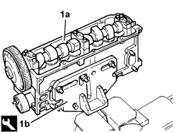
- Unscrew the bolt and remove the toothed driven pulley.
- Undo the nut and remove the mobile timing belt tensioner.
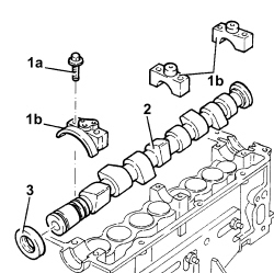
1. Undo bolts (1a) and remove camshaft caps (1b).
2. Remove the camshaft.
3. Remove the camshaft front oil seal.
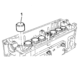
1. Remove the tappet sleeves complete with adjustment shims.
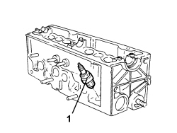
1. Remove the spark plugs.
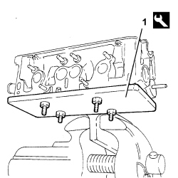
1. Fit the valve retaining tool beneath the cylinder head.
| Tool | Description | Function | Validity |
|---|---|---|---|
| 1.860.749.000 | Stand | Valve support | 1.2 8V 1.3 Mjet |
1. Remove half-cones (1a) using tools (1b) and (1c).
| Tool | Description | Function | Validity |
|---|---|---|---|
| 1.860.644.001 | Lever | Removing/ refitting valves | 1.2 8V 1.3 Mjet |
| Tool | Description | Function | Validity |
|---|---|---|---|
| 1.870.890.000 | Chamber | Valve cotter removal | 1.2 8V 1.4 16V |
2. Fit the upper valve shims.
3. Remove the valve springs.
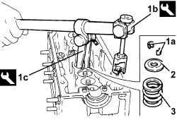
1. Use the tool (1a) to remove the oil seals (1b).
2. Fit the lower valve shims.
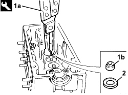
- Replace the valve guides
Op. 1016E14 VALVE GUIDES IN SINGLE CYLINDER HEAD - REPLACE DURING OP. 1016E10
Refitting
- Clean any traces of the old gasket from the lower cylinder head surface.
Op. 1016E38 SINGLE CYLINDER HEAD OR (ONE) LEFT OR RIGHT, REMOVED - GRINDING
- Check that the diameter of the valve stems corresponds to the recommended figures; if not, replace the worn valves.
| Measurement | Value | Validity |
|---|---|---|
| Inlet valve stem diameter | 4.982 ÷ 5.000 | 1.2 8V |
| Measurement | Value | Validity |
|---|---|---|
| Exhaust valve stem diameter | 4.974 ÷ 4.992 | 1.2 8V |
- Check that the diameter of the valve head corresponds to the recommended figures; if not, replace the valves.
| Measurement | Value | Validity |
|---|---|---|
| Inlet mushroom valve diameter (mm) | 33.10 ÷ 33.30 | 1.2 8V |
| Measurement | Value | Validity |
|---|---|---|
| Exhaust mushroom valve diameter (mm) | 27.80 ÷ 28.10 | 1.2 8V |
- Check that the length of the valve springs released is within the recommended values.
| Measurement | Value | Validity |
|---|---|---|
| Valve spring free length (mm) | 42.29 | 1.2 8V |
- Check that the measurements for the valve springs are within the recommended values.
| Measurement | Value | Validity |
|---|---|---|
| Length of valve springs under a load of 15.5 daN (mm) | 35.10 | 1.2 8V |
| Measurement | Value | Validity |
|---|---|---|
| Length of valve springs under a load of 39 daN (mm) | 26.30 | 1.2 8V |
- Clean the valve seats thoroughly.
- Check that the diameter of the camshaft journals corresponds to the recommended figures; if not, replace the camshaft.
| Measurement | Value | Validity |
|---|---|---|
| Camshaft bearing diameter - First bearing (mm) | 24.000 ÷ 24.015 | 1.2 8V |
| Measurement | Value | Validity |
|---|---|---|
| Camshaft bearing diameter - Second bearing (mm) | 23.500 ÷ 23.515 | 1.2 8V |
| Measurement | Value | Validity |
|---|---|---|
| Camshaft bearing diameter - Third bearing (mm) | 30.992 ÷ 31.008 | 1.2 8V |
- Check that the nominal camshaft cam lift corresponds to the recommended figures; if not, replace the worn camshaft.
| Measurement | Value | Validity |
|---|---|---|
| Nominal camshaft cam lift (mm) | 9.5 | 1.2 8V |
- Check that the diameter of the cylinder head camshaft tappet sleeve housings corresponds to the recommended figures; if not, replace the cylinder head.
| Measurement | Value | Validity |
|---|---|---|
| Tappet sleeve outer diameter (mm) | 34.975 ÷ 34.995 | 1.2 8V |
- Check that the diameter of the cylinder head camshaft tappet sleeve housings corresponds to the recommended figures; if not, replace the cylinder head.
| Measurement | Value | Validity |
|---|---|---|
| Tappet sleeve seat diameter (mm) | 35.015 ÷ 35.030 | 1.2 8V |
- Fit the thermostat complete with a new gasket and secure it using the bolts.
- Fit the moving timing belt tensioner and secure it with the nut without tightening.
- Fit the valve retaining tool after positioning the valves in their seats.
| Tool | Description | Function | Validity |
|---|---|---|---|
| 1.860.749.000 | Stand | Valve support | 1.2 8V 1.3 Mjet |
1. Fit the lower valve shims.
2. Fit the valve guide oil seals (2a) using the tool (2b).
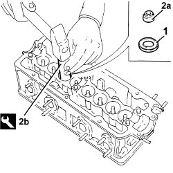
- Fit the valve springs, the upper valve shims and the half-cones using the same tool as for the removal.
- Remove the valve retaining tool fitted previously.
- Fit the camshaft tappet sleeves complete with adjustment shims.
- Fit the camshaft on the cylinder head.
- Fit the camshaft caps and secure them by tightening the bolts to the recommended torque.
| Component | Fastening | dia | Value (daNm) | Validity |
|---|---|---|---|---|
| Camshaft caps | Bolt | M8x1.25x53 | 2.0 | 1.2 8V |
| Component | Fastening | dia | Value (daNm) | Validity |
|---|---|---|---|---|
| Camshaft caps | Bolt | M6x1x32 | 0.9 | 1.2 8V |
- Fit the oil seal with the tool.
| Tool | Description | Function | Validity |
|---|---|---|---|
| 1.860.882.000 | Fitting tool | Fitting camshaft oil seal | 1.2 8V |
- Fit the toothed driven pulley by tightening the bolt provisionally.
Removing
CYLINDER HEAD EXTENSION
1. Position cylinder head extension (1a) in a vice using tool (1b).
| Tool | Description | Function | Validity |
|---|---|---|---|
| 1.860.470.000 | Mount | Head overhaul | all versions |
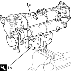
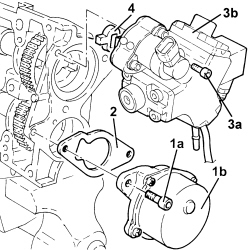
1. Undo bolts (1a) and remove vacuum pump (1b).
2. Remove the gasket.
3. Undo bolts (3a) and remove pressure pump (3b) complete with O-ring.
4. Remove the joint.
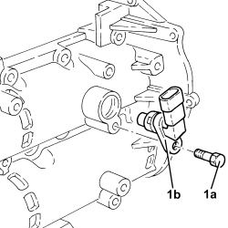
1. Undo bolt (1a) and remove cam angle sensor (1b).
- Temporarily remove the tool fitted previously on the exhaust side camshaft.
| Tool | Description | Function | Validity |
|---|---|---|---|
| 1.870.896.900 | Templates | Engine tuning | 1.3 Mjet |
- Check that the camshaft endfloat is within the recommended values using a dial gauge.
| Measurement | Value | Validity |
|---|---|---|
| Camshaft end float (mm) | 0.15 ÷ 0.34 | 1.3 Mjet |
- If the camshaft endfloat value is not within the recommended values, replace the worn components when reassembling the cylinder head.
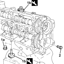
1. Remove plug (1a) and fit tool (1b) on the intake side camshaft.
Fit the tool, positioning it with the millings horizontal and checking that it is correctly inserted in the camshaft housing.
| Tool | Description | Function | Validity |
|---|---|---|---|
| 1.870.896.900 | Templates | Engine tuning | 1.3 Mjet |
2. Undo the bolts securing the camshaft gears.
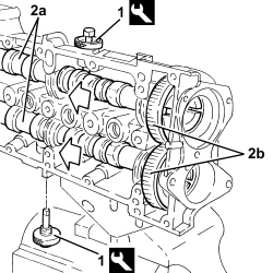
1. Remove the camshaft timing tools for the cylinder head extension.
| Tool | Description | Function | Validity |
|---|---|---|---|
| 1.870.896.900 | Templates | Engine tuning | 1.3 Mjet |
2. Release camshafts (2a), as necessary and remove camshaft gears (2b).
- Completely remove the camshafts.
- Remove the support tool complete with camshaft housing from the vice and separate them.
CYLINDER HEAD
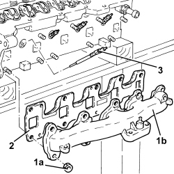
1. Undo nuts (1a) and remove exhaust manifold (1b).
2. Remove the exhaust manifold gasket.
3. Unscrew the glow heater plugs and remove.
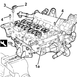
1. Position cylinder head (1a) in a vice using tool (1b).
| Tool | Description | Function | Validity |
|---|---|---|---|
| 1.860.470.000 | Mount | Head overhaul | all versions |
2. Remove the valve rockers.
3. Remove the hydraulic tappets.
4. Remove the cylinder head extension locating bushes.
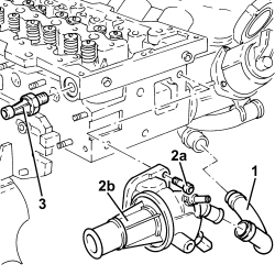
1. Loosen the collars and remove the coolant delivery sleeve from the thermostat to the coolant/exhaust gas heat exchanger for the EGR system.
2. Undo bolts (2a) and remove thermostat (2b) complete with O-ring.
3. Undo and remove the engine oil pressure warning light switch.
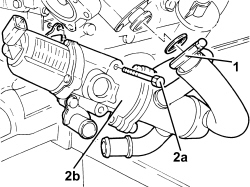
1. Loosen the collar securing the exhaust gas/coolant heat exchanger for the EGR system, air chamber side.
2. Undo bolts (2a) and remove coolant/exhaust gas heat exchanger for E.G.R. system (2b).
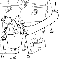
1. Release the engine oil vapour recirculation pipe for the retaining band on the air capacity chamber.
2. Unscrew bolts (2a) and remove engine oil vapour separator (2b) complete with engine oil vapour recirculation pipe (2c).
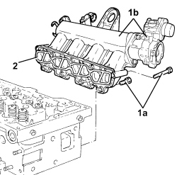
1. Undo bolts (1a) and remove air capacity chamber (1b) complete with excess pressure sensor.
2. Remove the gasket.
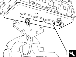
1. Fit a wooden stand on the cylinder head plane to support the valves and secure it using bolts.
| Tool | Description | Function | Validity |
|---|---|---|---|
| 1.860.749.000 | Stand | Valve support | 1.2 8V 1.3 Mjet |
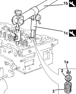
1. Remove half-cones (1a) using tools (1b) and (1c).
| Tool | Description | Function | Validity |
|---|---|---|---|
| 1.860.644.001 | Lever | Removing/ refitting valves | 1.2 8V 1.3 Mjet |
| Tool | Description | Function | Validity |
|---|---|---|---|
| 1.870.881.000 | Chamber | Removing/ refitting valves | 1.3 Mjet |
2. Remove the valve upper shim.
3. Remove the valve spring.
- Carry out the same operations on the other valves.
- Remove the wooden stand and keep the valves.
| Tool | Description | Function | Validity |
|---|---|---|---|
| 1.860.749.000 | Stand | Valve support | 1.2 8V 1.3 Mjet |
1. Remove valve guide oil seals (1a) using tool (1b).
| Tool | Description | Function | Validity |
|---|---|---|---|
| 1.870.894.000 | Calliper | Removing valve guide oil seals | 1.3 Mjet 1.4 16V |
2. Fit the lower valve shims.
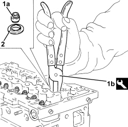
- Remove the cylinder head from the support tool.
- Replace the valve guides
Op. 1016E14 VALVE GUIDES IN SINGLE CYLINDER HEAD - REPLACE DURING OP. 1016E10
Refitting
- Clean any traces of the old gasket from the lower cylinder head surface.
- Clean traces of the oil gasket off the mating surfaces between the cylinder head and the cylinder head extension.
- Check that the flatness of the lower cylinder head surface corresponds to the recommended values.
| Measurement | Value | Validity |
|---|---|---|
| Cylinder head lower support surface flatness (mm) | 0.1 | 1.3 Mjet |
- If the lower surface flatness of the lower cylinder head is not within the specified values, grind from the nominal head height and then fit a new gasket with the number of notches determined as described below.
- The head may be levelled to 0.1 m if starting from a gasket with 0 notches and using a new gasket with 1 notch.
- The head may be levelled to 0.2 m if starting from a gasket with 0 notches and using a new gasket with 2 notches.
- The head may be levelled to 0.1 m if starting from a gasket with 1 notch and using a new gasket with 2 notches.
When within limit conditions (head gasket with 2 notches before levelling), the lower cylinder head surface cannot be levelled.
| Measurement | Value | Validity |
|---|---|---|
| Cylinder head nominal height (mm) | 105.5 ± 0.05 | 1.3 Mjet |
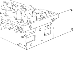
- Check that the valves do not show signs of grooves or seizing.
- Check that the diameter of the valve stems corresponds to the recommended figures; if not, replace the worn valves.
| Measurement | Value | Validity |
|---|---|---|
| Valve stem/inlet valve diameter - exhaust (mm) | 5.90 ± 5.94 | 1.3 Mjet |
- Check that the length of the valve springs released is within the recommended values.
| Measurement | Value | Validity |
|---|---|---|
| Valve spring free length (mm) | 37.9 | 1.3 Mjet |
- Using a torque wrench, check that the valve spring specifications correspond to the recommended figures; if not, replace the worn components.
| Measurement | Value | Validity |
|---|---|---|
| Length of valve springs under a load of 16.2 - 18.0 daN (mm) | 31.0 | 1.3 Mjet |
| Measurement | Value | Validity |
|---|---|---|
| Length of valve springs under a load of 36.1 - 39.5 daN (mm) | 23.5 | 1.3 Mjet |
- Check that the diameter of the camshaft bearings corresponds to the recommended figures; if not, replace the worn camshaft/s.
| Measurement | Value | Validity |
|---|---|---|
| Camshaft bearing diameter - First bearing (mm) | 38.500 ÷ 38.515 | 1.3 Mjet |
| Measurement | Value | Validity |
|---|---|---|
| Camshaft bearing diameter - Second bearing (mm) | 38.000 ÷ 38.015 | 1.3 Mjet |
| Measurement | Value | Validity |
|---|---|---|
| Camshaft bearing diameter - Third bearing (mm) | 30.000 ÷ 30.015 | 1.3 Mjet |
- Check that the nominal camshaft cam lift corresponds to the recommended figures; if not, replace the worn camshaft/s.
| Measurement | Value | Validity |
|---|---|---|
| Nominal inlet cam lift (mm) | 6.4 | 1.3 Mjet |
| Measurement | Value | Validity |
|---|---|---|
| Nominal exhaust cam lift (mm) | 7.5 | 1.3 Mjet |
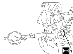
1. Check that the diameter of the camshaft supports corresponds to the recommended figures; if not, replace the cylinder head.
| Measurement | Value | Validity |
|---|---|---|
| Camshaft support diameter - First support | 38.545 ÷ 38.570 | 1.3 Mjet |
| Measurement | Value | Validity |
|---|---|---|
| Camshaft support diameter - Second support | 38.045 ÷ 38.070 | 1.3 Mjet |
| Measurement | Value | Validity |
|---|---|---|
| Camshaft support diameter - Third support | 30.045 ÷ 30.070 | 1.3 Mjet |
1. Grind the valve seats to the recommended size.
| Measurement | Value | Validity |
|---|---|---|
| Valve seat band angle in contact with valve | 45° ± 20' | 1.3 Mjet |
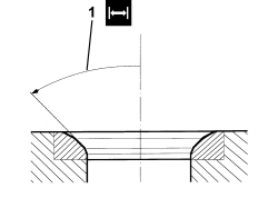
- Grind the valve seats using a suitable tool.
CYLINDER HEAD
- Position the cylinder head in the vice using the tool.
| Tool | Description | Function | Validity |
|---|---|---|---|
| 1.860.470.000 | Mount | Head overhaul | all versions |
- Fit the valves in the seats, then support them using the wooden stand and secure it using suitable bolts.
| Tool | Description | Function | Validity |
|---|---|---|---|
| 1.860.749.000 | Stand | Valve support | 1.2 8V 1.3 Mjet |
- Place the lower valve shims in their housings.
1. Fit valve guide oil seals (1a) in their seats using tool (1b).
| Tool | Description | Function | Validity |
|---|---|---|---|
| 1.870.900.800 | Installing tool | Valve guide oil seal fitting | 1.3 Mjet |
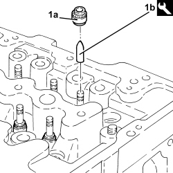
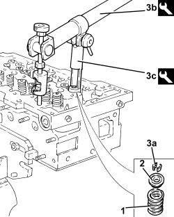
1. Fit the valve spring in its seat.
2. Refit the upper valve shim.
3. Place half-cones (3a) in their housings using tools (3b) and (3c).
| Tool | Description | Function | Validity |
|---|---|---|---|
| 1.860.644.001 | Lever | Removing/ refitting valves | 1.2 8V 1.3 Mjet |
| Tool | Description | Function | Validity |
|---|---|---|---|
| 1.870.881.000 | Chamber | Removing/ refitting valves | 1.3 Mjet |
- Carry out the same operations on the other valves.
- Remove the wooden stand for supporting the valves from the cylinder head plane.
| Tool | Description | Function | Validity |
|---|---|---|---|
| 1.860.749.000 | Stand | Valve support | 1.2 8V 1.3 Mjet |
- Refit the air chamber complete with gasket and excess pressure sensor back in its housing and secure it by tightening the bolts to the recommended torque.
| Component | Fastening | dia | Value (daNm) | Validity |
|---|---|---|---|---|
| Intake manifold (on cylinder head) | Bolt | M8x1.25x65 | 2.5 | 1.3 Multijet |
| Component | Fastening | dia | Value (daNm) | Validity |
|---|---|---|---|---|
| Intake manifold (on cylinder head) | Bolt | M8x1.25x20 | 2.5 | 1.3 Multijet |
- Replace the engine oil vapour separator with engine oil vapour recirculation pipe in its seat and secure with bolts.
- Fasten the engine oil vapour recirculation pipe to the band on the air capacity chamber.
- Place the exhaust gas/coolant heat exchanger for the E.G.R. system, complete with gasket, back in its housing and secure it by tightening the bolts to the specified torque.
| Component | Fastening | dia | Value (daNm) | Validity |
|---|---|---|---|---|
| E.G.R. valve (on cylinder head) | Bolt | M8x1.25x90 | 2.2 | 1.3 Multijet |
- Replace the engine oil pressure warning light switch in its housing and tighten it to the recommended torque.
| Component | Fastening | dia | Value (daNm) | Validity |
|---|---|---|---|---|
| Engine oil pressure switch | M14x1.5 | 3.2 | all versions |
- Replace the thermostat in its housing with the O-ring and secure it by tightening the bolts to the recommended torque.
| Component | Fastening | dia | Value (daNm) | Validity |
|---|---|---|---|---|
| Thermostat unit (on cylinder head) | Bolt | M8x1.25x22 | 2.5 | 1.3 Multijet |
- Replace the coolant delivery sleeve from the thermostat to the coolant/exhaust gas heat exchanger for the EGR system and secure with the relevant bands.
- Refit the cylinder head extension locating bushes in their seats in the cylinder head.
Before fitting the locating bushes, check that the height is 13 mm.
- Place the hydraulic tappets in their housings.
Position the hydraulic tappets with the oil channel hole turned toward the outside of the cylinder head: this position brings the hole into communication with the oil duct on the lower cylinder head.
- Place the valve rockers in their housings.
- Remove the cylinder head from the support tool.
| Tool | Description | Function | Validity |
|---|---|---|---|
| 1.860.470.000 | Mount | Head overhaul | all versions |
- Place the glow heater pugs in their housings.
- Place the exhaust manifold gasket in its housing.
- Place the exhaust manifold in its housing and secure it by tightening the nuts to the recommended torque.
| Component | Fastening | dia | Value (daNm) | Validity |
|---|---|---|---|---|
| Exhaust manifold (on cylinder head) | Nut | M8x1.25 | 1.5 + 30° | 1.3 Multijet |
CYLINDER HEAD EXTENSION
- Position the cylinder head extension in the vice using the tool.
| Tool | Description | Function | Validity |
|---|---|---|---|
| 1.860.470.000 | Mount | Head overhaul | all versions |
- Place the camshafts in their housings.
- Refit the camshaft gears in their housings and secure them without tightening the bolts.
1. Fit the camshaft timing tools.
Fit the tools and position with their millings horizontal. Ensure they fit into the seats on the camshafts.
| Tool | Description | Function | Validity |
|---|---|---|---|
| 1.870.896.900 | Templates | Engine tuning | 1.3 Mjet |
2. Tighten the camshaft gear bolts to the recommended torque.
| Component | Fastening | dia | Value (daNm) | Validity |
|---|---|---|---|---|
| Camshsaft idler gear (inlet side) | Bolt | M12x1.25x33 | 15.0 | 1.3 Multijet |
| Component | Fastening | dia | Value (daNm) | Validity |
|---|---|---|---|---|
| Camshsaft idler gear (exhaust side) | Bolt | M12x1.25x33 | 15.0 | 1.3 Multijet |
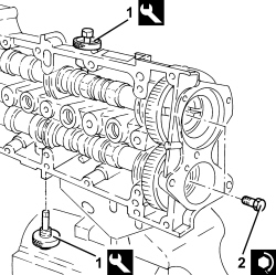
- Position the cam angle sensor in its housing and secure it using the bolt.
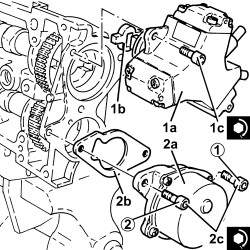
1. Position pressure pump (1a), complete with coupling (1b) and a new o-ring, in its housing and secure it by tightening bolts (1c) to the recommended torque.
| Component | Fastening | dia | Value (daNm) | Validity |
|---|---|---|---|---|
| Injection pump | Bolt | M7x1x20 | 1.5 | 1.3 Multijet |
2. Place vacuum pump (2a), complete with gasket (2b), back in its housing and secure it by tightening bolts (2c) to the recommended torque.
| Component | Fastening | dia | Value (daNm) | Validity |
|---|---|---|---|---|
| Vacuum pump (on cylinder head extension) | Bolt | M8X1,25X22 | 2.0 | T.i.T |
Follow the order shown in the diagram for each tightening sequence. The tightening to 2.0 daNm is performed in two stages: a pre-tightening to 0.5 daNm followed by an additional tightening of 1.8 - 2.2 daNm.
- Remove the support tool complete with cylinder head extension from the vice and separate them.
Parts & tools for this job For 2007 Fiat 500
- PARTEngine gasket setSearch: Fiat 500 2007 engine gasket set
- TOOLTorque wrenchSearch: 3/8 inch torque wrench
- TOOLFeeler gauge setSearch: feeler gauge set
Links open Amazon search results in a new tab. As an Amazon Associate I earn from qualifying purchases.