
Introduction
- Make
- Fiat
- Model
- 500 Factory Service Manual
- Year
- 2007–2024
- Section
- General › Introduction
INTRODUCTION
INTRODUCTION
The topics are covered with particular attention given to the new technical features required for passing the various tests introduced by new legislation. The descriptions and operating information provided are limited to a discussion of principles, rules and minimum precautions.
For information on repair methods and vehicle technical specifications, see the specific sections on repair procedures.
Aerodynamics
The styling of the new car is designed to reflect great personality and originality and improves on the attributes of roominess, practicality and sturdiness achieved by previous models.
The front, sides, rear and underbody were developed with particular attention to aerodynamics and to allow outstanding drag coefficient values.
Safety
The main aim of car manufacturers is definitely the total safety of the driver and passengers.
To adapt the vehicle to highly demanding European and international market regulations, the new Fiat vehicle was designed with great attention to detail in order to achieve an optimum response in all situations.
Passive safety
A vehicle''s passive safety is the collection of technical and product solutions designed to protect the occupants of the vehicle in the case of an accident.
The search for excellent performance has led to the introduction of design and construction solutions on the new vehicle that represent the state of the art in the field of passive safety.
The safety features guaranteed by the vehicle stem from the thorough integration of the structural components, the high number of specific devices that make up the occupant protection system and the special devices used in the design of the interior and exterior components.
The occupant protection system
The vehicle is equipped with a basic occupant protection system on all trim levels composed of:
- front Air Bag protection system comprising driver and passenger front Air Bags with a dual activation system;
- front belts with dual pretensioner and load limiter;
- electronic Air Bag disabling system (my car).
The following optional features are also available:
- two Bags on the front seats, guaranteeing protection for the chest and pelvis;
- two head bags housed in the side members under the roof, guaranteeing protection for the head against highly intrusive objects.
- an Air Bag protecting the driver''s knees;
For more information on the Air Bag system see.
See descriptions 5580C AIR BAG SYSTEM
In addition to passenger safety, particular attention has been paid to child safety and pedestrian safety.
The child safety system includes all those devices that offer the best protection currently available such as isofix mountings on the rear seats and the inhibition of the passenger air bag directly by the control panel.
The solutions adopted in the design and manufacture of the seats, the dashboard and the interior panels and fittings increase the vehicle''s level of passive safety.
For more information on these topics, refer to the specific chapters.
Resistance to impacts
All the features relating to Passive Safety have been developed in order to offer the maximum protection for the occupant in all possible impact situations at high speed:
- frontal impact
- rear impact
- side impact
- roll over.
The behaviour of the body in crash tests has more than adequately satisfied the international safety standards.
Pedestrian protection
The style of the front part of the vehicle has been developed taking into account the protection of pedestrians as required by the most recent international legislation. The shapes are smooth and rounded and there are no unsafe projections for the safety of pedestrians. The ample surface area of the bonnet minimizes the risk of contact between pedestrian''s heads and the rigid front pillars.
The most rigid components are located inside the engine compartment a suitable distance away from the bonnet in order to allow the bonnet skin to absorb the energy forces of the impact with the pedestrian''s head.
Resistance to twisting and bending forces
The vehicle''s high resistance to twisting and bending forces ensures good properties of passive strength and also offers a number of benefits:
- low noise due to fewer vibrations;
- no creaking from the trim;
- better handling by maintaining the correct suspension angles and thus an absolutely controlled drive for a sensation of stability and comfort in general,
- greater ability to withstand breakages caused by using the vehicle over particularly uneven road surfaces;
- sensation of vehicle compactiness;
- to ensure long-term overall vehicle quality.
Torsional rigidity
Torsional rigidity figures:
- Body with bonded windscreen: 81000 daNm/rad
- Body without bonded windscreen: 71000 daNm/rad
Figures for resistance to bending:
- Body with bonded windscreen: 1150 daN/mm
First vibration mode:
The high value of the vibration mode indicates high static torsional rigidity with an optimum distribution and use of the mass guaranteeing the minimum weight of the vehicle with excellent vibro-acoustic qualities, such as:
- structural vibration and interior noise during acceleration and in a steady gear
- comfortable engine idle speed
- good behaviour on uneven road surfaces
- quiet in passenger compartment
- no coupling noise between interior trims
- vehicle dynamic compactness
First torsional mode: 38Hz.
Bodyshell protection
Anti-corrosion design
The bodyshell has been designed to withstand environmental conditions in the most severe markets such as Central Northern Europe where salt is used on the roads to prevent freezing.
Design features have been introduced with this in mind to guarantee complete accessibility of the body to the protection and painting processes (in particular the anti-rust treatments and cataphoresis) and ensuring that all the elements are the correct shape to prevent any possible dampness forming in the internal structures.
This includes the design of the panel joins (shape and dimensions) in order to make them suitable for the sealing operations, which is essential both in terms of water tighteness and sound inslation of the vehicle.
A fundamental part of the design is also the choice and usage of galvanized panels for all elements of the bodyshell exposed to the potential risk of corrosion.
Galvanized panels
The zinc deposited in a continuous layer on the surface of the panel constitutes the first line of defence against corrosion of the steel. The zinc layer acts as an active chemical protection for the steel, known as a sacrificial layer, that combines with the subsequent protective systems to guarantee outstanding long-term corrosion-proofing.
The galvanizing of the panels takes place directly through two different technological processes, both capable of ensuring constant thicknesses of zinc with a high standard surface finish:
- Galvanizing: the panel is immersed in a solution of zinc salts and a layer of pure zinc is deposited by means of the electrolytic effect; the normal thickness of the zinc deposit is 8 - 10 micron.
- Hot galvanizing: molten zinc is deposited on the panel due to the effect of heat. In this case too the normal thickness of the zinc is 8 - 10 micron, but thicknesses of up to 20 micron can be reached using this process and it should be used for the parts most exposed to corrosion.
The two processes allow galvanizing on both sides of the panel.
It is therefore possible to produce simultaneous protection for both the inside and the outside of all panels and, in particular, protection of the surfaces in contact with several elements welded together.
Panels galvanized on both sides account for 90% of the vehicle body weight.
In particular, all the parts that make up the chassis, most exposed to corrosive agents, are 100% galvanized.
Of these, the structures defined as safety structures, such as the suspension mountings and reinforcements for the seat belts, are made from panels with a high zinc thickness, up to 20 micron.
The body is made entirely from 8 micron galvanized panels for the doors, bonnet, boot lid, side panels, wings and roof.
The exception is some of the inner parts of the passenger compartment because there is no risk at all of oxidation such as, for example, the dashboard mounting brackets.
Anti-corrosion test
All the anti-corrosion provisions made have been subjected to laboratory tests and they have performed well in accelerated tests on vehicles carried out in special test areas, where the most stringent conditions of the central-northern European markets have been reproduced.
Anti-corrosion goals
The anti-corrosion provisions adopted make it possible to satisfy the following anti-corrosion guarantees:
- 3 years of the vehicle''s life without cosmetic corrosion points
- 8 years of the vehicle''s life without panel perforation in the harshest Northern European climates.
In addition, the protective package made up of medium-high thickness galvanized panels plus cataphoretic treatment of the entire structure makes it possible to comply with the European regulations concerning safety features (10 years of the vehicle''s life without structural weaknesses).
Painting
Specifications of the painting cycle
The aim of painting the body is to:
- protect the sheet metal against corrosion due to exposure to environmental effects;
- achieve high levels of gloss and colour richness and maintain them in time.
Before being painted the body undergoes a pre-treatment process known as bonderization during which an initial degreasing stage is followed by a phosphating treatment.
The latter forms a crystalline layer of phosphate which make up the base on which the subsequent painting layer is applied through cataphoresis.
Painting through cataphoresis is a fundamental treatment for the protection of the structural elements.
It allows the paint to be deposited in areas of the body that would otherwise be inaccessible, such as the internal box structures.
The process takes place through immersion in an electrically insulated vat containing an aqueous solution of paint product.
The solution is negatively charged, whilst the body is positively charged. During immersion, a layer of paint is deposited (22 microns on horizontal parts and 20 microns on vertical parts). This can be adjusted by altering the bath voltage, the bath temperature and the length of time the body remains in the solution.
The body then undergoes a process of stoving in an oven at 160° for around 20 minutes.
Sound-proofing materials are then applied to the prepared body and all the joints between the body panels are sealed to prevent corrosive agents leaking through.
The body is now prepared by adding a primer coat (30 microns thick) before undergoing a further stoving cycle in the oven.
Lastly, the aesthetic finish is applied comprising a layer of enamel base coat (colour) followed by a clear resin coat with very good resistance properties to outside agents (humidity, the sun''s rays) and the final baking in the oven.
Environmentally-friendly, water-based enamels are used at the production plant.
The table illustrates the painting process for the vehicle.
Bodyshell painting cycle
| DEGREASING | BONDERIZATION The body is cleaned down to the panel surfaces and a layer of phosphate micro crystals is deposited. This forms an ideal base for the subsequent painting. |
| PHOSPHATING | |
| CATAPHORESIS | APPLICATION OF CATAPHORESIS All the inner and outer surfaces of the body are covered in a layer of anti-rust paint through a cataphoretic process. The layer deposited is then stoved in an oven. |
| STOVING | |
| SEALING, SOUND INSULATION AND UNDERBODY PROTECTION | APPLICATIONS FOLLOWING CATAPHORESIS The bodyshell receives all the materials necessary for sealing, sound insulation of the vehicle and the protection of the outer floor from the effects of stone chipping. It then receives the paint base coat which is the ideal base for the subsequent aesthetic painting. All these materials are stoved in a special oven. |
| PAINT BASE COAT | |
| STOVING | |
| ENAMEL + CLEAR RESIN | APPLICATION OF THE ENAMEL The body receives the enamel layer on all the visible surfaces and then the clear resin with good aesthetic properties and high resistance to environmental agents. |
| STOVING |
Identification
The vehicle colour range includes:
- pastel colours;
- metallic colours.
Both are produced through the application of a pastel or metallic base coat and clear resin (double layer).
The vehicle colour type and specifications are shown on the identification plate which carries the following information.
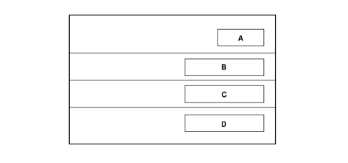
A. enamel supplier (coloured base)
B. colour name
C. colour code
D. type of product to be used for touching up and painting in the event of service operations
Recycling of materials
Main specifications
According to EEC ELV (End of Life Vehicles) directives, all metallic and non-metallic parts must be recovered from the vehicle and reused, 80% to produce new material and 5% for recovered energy. Nowadays, some 75% of a vehicle''s weight is made up of metal that can easily be recovered by melting when different metals can be separated by heating to their different melting points.
All the remaining part of the vehicle, amounting to 25% by weight, must currently be recovered before this stage.
Research is in progress so that one day separation can take place after the crushing of motor vehicle bodies, in accordance with post-shredding technologies, known by the English term Post-Shredding Technologies (PST).
The solution to the problem of recycling plastics is resolved at the design stage: the possibility of re-using the material on future components must be assessed at this time.
The aims to be considered at the design stage include:
- ease of component disassembly;
- choice of noble materials in the recyclable polymer chain (giving priority to parts made up of a single family, e.g. PP).
A part cannot be recycled to produce a part that is the same as the original part because the material may not be able to guarantee the necessary levels of reliability or it may not be financially viable.
Plastics may be recycled in a cascade pattern, for example:
- insulating material for the building industry is obtained from seat padding;
- the material used to line the wheel arches is obtained from the bumpers and then goes on to produce sound-proofing elements. In the end, it becomes a fuel for energy production.
This model has been designed to ensure that all its plastic and elastomer parts (rubbers) weighing over 100 grams are marked with coded symbols to identify the material during recycling and also to ensure that all its components are recyclable.
In particular, the impacts that could be exerted on the environment both during the life cycle of the product and during the scrapping stage are already analyzed during the design stage. In some cases the choice of materials has been made using an innovative evaluation system known as L.C.A. (Life Cycle Assessment) which makes it possible to assess the effects on the environment globally, taking into account not only the engineering and industrial specifications of the materials, but also the environmental critical areas during the production of the raw materials during usage and at the end of life.
Great emphasis has been placed on improving this model''s recyclability: technological solutions in single materials have been favoured and the polymer families present have been further reduced.
The recyling process therefore afffects three successive vehicle generations to help save raw materials. Other materal reuse processes are also being examined outside the motor industry, following the lead taken by the F.A.Re (Fiat Auto Recycling) partnership in the Eighties and Nineties.
Another important point to note concerns the use of heavy metals in the motor industry. The metals in question are hexavalent chrome (Cr6), mercury (Hg), cadmium (Cd) and lead (Pb). These are banned (Cr6) or permitted only in tiny amounts when their use must be indicated by labelling or by including information in the documents supplied with the vehicle.
The tables in the chapter "GENERAL INFORMATION AND TECHNICAL DATA - OPERATING DATA" show symbols for, and descriptions of, recyclable materials present on the vehicle. This is to ensure that the best available products are used for washing the interior, painting of plastic parts and carrying out repairs, bonding etc. The aim is to avoid the possibility of damage by using incompatible products. Labelling also allows organic materials to be selected on the basis of their chemical composition. During servicing, it is also advisable to separate materials on the basis of their composition to ensure that they can be recycled more easily.
Panels
Technical aspects
Over the last 10 years the resistance to traction of structural steel has tripled. These are high strength steels if the attrition load is less than 310 MPa and ultra-high strength if a figure of at least 450 MPa is reached. High strength steels have a specific weight that can be compared with that of traditional steel.
The mechanical properties of high strength steels depends on the phosphorous and manganese silicates present in small quantities and on the extremely low carbon content.
HSLA steels (high strength low alloy) have particles with reduced dimensions and consequently high resistance and excellent mouldability when cold.
Multiphase steels have an even better mouldability/attrition ratio since the very tough basic structure incorporates other high strength phases (e.g. Dual Phase steels) containing 5 - 20% martensite dispersed in ferrite. The resistance increases during machining.
Trip (Tranformation induced plasticity) is a steel with an attrition limit above 700 MPa which contains a large amount of residual austenite which, when deformation takes place, is transformed into martensite: this produces extremely high resistance to fatigue and good deformability.
The properties of high strength steels deteriorate over time: they cannot be stored for long periods. As far as rigidity and fatigue are concerned, their behaviour is exactly the same as low carbon content steels.
The world of the car
The use of high strength steels by manufacturers has increased considerably over recent years; nowadays the problem of repairing high strength steel panels is of current significance.
The producers of high strength steels have put forward new solutions capable of competing with aluminium alloys.
High strength steels: types and properties
Long band rolling-mills, cold rolling-mills, the extensive check on procedures and continuous annealing are at the basis of the new generation of high strength panels produced in various types.
Rephosphorated steels are being increasingly used in automotive engineering: the panels, produced in thicknesses of less than 0.25 to 0.5 mm have good mouldability, deep-drawing and stretching properties. Their strength is due to the small amounts of phosphorous and manganese silicates and the extremely low carbon content which improves mouldability even further.
HSLA steels have increased resistance and excellent mouldability when cold through the reduced dimensions of the particles produced with small quantities of NbCN and TiC alloy precipitates. The thin HSLA steel panels are pressed and those with a thickness of more than 2 mm allow small bending radii.
Multiphase steels have an even better mouldability/attrition ratio. This feature is achieved by incorporating other high strength phases in the basic structure made up of very tough phases; in particular, in Dual Phase steels the final microstructure comprises 5 - 20% martensite dispersed in ferrite. These are high attrition steels, produced in very thin densities, sufficiently mouldable and with a high hardening capacity.
High percentages of hard phases, together with extremely fine precipitations of soft phases are a feature of steel microstructures with an attrition limit above 700 MPa. Trip steel (Transformation induced plasticity) has a high percentage of residual austentite which tends to transform into martensite when deformation takes place which confers extremely high resistance to fatigue and good deformability. The cost of production, high flexible return and wear of the tools used for machining are, however, problems.
The current development of high strength steels is directed, in the main, at improving machinability for plastic deformation: high mouldability can be produced, without a reduction in mechanical properties, through the continuous re-annealing of the panels when cold. BH steel is designed for good presing qualities: after deformation the resistance increases through an ageing mechanism through carbon activated by a painting cycle.
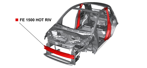
The bodyshell components made from FE 1500 HOT RIV steel (that cannot be repaired) are illustrated in the diagram below.
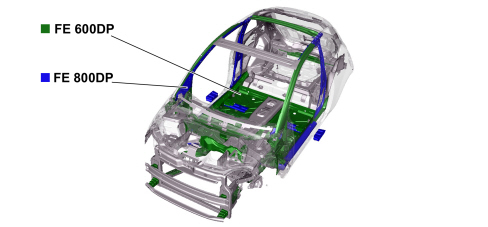
The bodyshell components made from FE 800 DP F steel and FE 600 DP F ultra strength steel are illustrated in the diagram below.
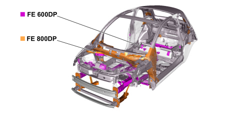
The bodyshell components made from FEE 355 steel and FEE 340 high strength steel are illustrated in the diagram below.
Some figures relating to welding carried out using a spot welder are given in the table below purely by way of example.
| Standard panel thickness (mm) | Active electrode section diameter (mm) | Minimum rated welding current [A] | Maximum rated welding current [A] | Hot time (periods) | Force at the electrodes [daN] |
|---|---|---|---|---|---|
| 0,8 + 0,8 | 6 | 9000 | 11000 | 9 | 225 +/- 10 |
| 1 + 1 | 6 | 9000 | 11000 | 11 | 260 +/- 10 |
| 1,2 + 1,2 | 6 | 9000 | 11500 | 12 | 300 +/- 10 |
| 1,5 + 1,5 | 6 | 9500 | 11500 | 14 | 350 +/- 10 |
| 0,8 + 0,8 + 0,8 | 6 | 10000 | 12000 | 11 | 260 +/- 10 |
| 1 + 1 + 1 | 6 | 10000 | 12000 | 13 | 300 +/- 10 |
| 1,2 + 1,2 + 1,2 | 6 | 10000 | 12000 | 15 | 350 +/- 10 |
| 1,5 + 1,5 + 1,5 | 6 | 11000 | 13000 | 16 | 400 +/- 10 |
| 1,8 + 1,8 | 8 | 9000 | 11500 | 6 | 400 +/- 10 |
| 2 + 2 | 8 | 9000 | 12000 | 7 | 450 +/- 10 |
| 2,2 + 2,2 | 8 | 9500 | 12500 | 8 | 450 +/- 10 |
| 2,5 + 2,5 | 8 | 10000 | 13000 | 9 | 470 +/- 10 |
| 2,75 + 2,75 | 8 | 10700 | 13500 | 8 | 500 +/- 10 |
| 3 + 3 | 8 | 11000 | 14000 | 9 | 550 +/- 1 |
1 Period = 1/50 second
These figures are and should only be an example for high and ultra high strength materials; the parameter that changes the most is the "force at the electrodes" which increases from 10 to 30% depending on the increase in the thickness and properties of the material.
Obviously as it is not possible to provide specific details for every individual welding machine it will be the responsibility of the mechanic depending on the power of the equipment available to apply the logic described previously.
Parts & tools for this job For 2007 Fiat 500
- TOOLTrim removal tool kitSearch: trim removal tool kit
- PARTTouch-up paintSearch: Fiat touch up paint
- PARTPanel clip assortmentSearch: Fiat panel clips assortment
Links open Amazon search results in a new tab. As an Amazon Associate I earn from qualifying purchases.