
Introduction - engine oil lubrication circuit
- Make
- Fiat
- Model
- Bravo Factory Service Manual
- Year
- 2007–2014
- Section
- Engine lubrication › Introduction - engine oil lubrication circuit
INTRODUCTION - ENGINE OIL LUBRICATION CIRCUIT
DESCRIPTION OF COMPONENTS
ENGINE OIL PUMP
The engine oil is drawn in by the sump by means of the vacuum created by the rotation of the gears on the crankshaft.
There is a vacuum from the partition (2) for the gears as far as the oil sump suction head.
Pressure builds up in all engine supply ducts (4) starting from separation bulkhead (2).
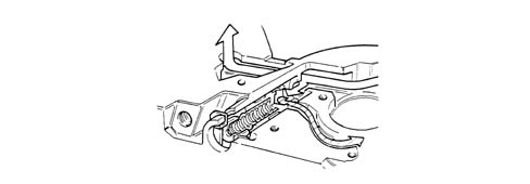
When the pressure exceeds 5 bar, the force exerted on the restricter valve (5) overcomes the reaction of the spring underneath and moves the valve until the connecting duct between the pressure chamber (3) and the low pressure chamber (1) opens.
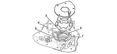
1 - Low pressure chamber
2 - Partition
3 - Pressure chamber
4 - Oil supply duct
5 - Oil pressure restricter valve
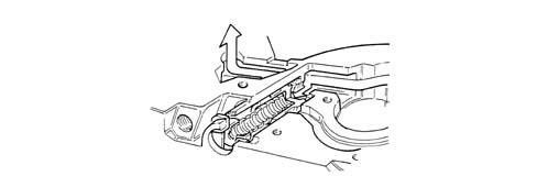
Engine oil pressure restricter valve closed operating position
Restricter valve short circuit operating position
Parts & tools for this job For 2007 Fiat Bravo
- PARTEngine gasket setSearch: Fiat Bravo 2007 engine gasket set
- TOOLTorque wrenchSearch: 3/8 inch torque wrench
- TOOLFeeler gauge setSearch: feeler gauge set
Links open Amazon search results in a new tab. As an Amazon Associate I earn from qualifying purchases.