
Front suspension crossmember - r.r
- Make
- Fiat
- Model
- Bravo Factory Service Manual
- Year
- 2007–2014
- Section
- Front suspension › Front suspension crossmember - r.r
FRONT SUSPENSION CROSSMEMBER - R.R
Removing
Op. 4450B12 FRONT WHEELS (TWO) - R+R
Op. 7055B65 ENGINE COMPARTMENT DUST COVER IN LEFT FRONT WHEEL ARCH - R.R.
Op. 7055B66 ENGINE COMPARTMENT DUST COVER IN RIGHT FRONT WHEEL ARCH - R.R.
Op. 1048A10 AIR FILTER ASSEMBLY - R.R.
Op. 1072C44 EXHAUST MANIFOLD HEAT SHIELD - R+R
Op. 4410D17 REINFORCEMENT FOR FRONT SUSPENSION CROSSMEMBER - R.R.
Op. 7055B54 UNDER ENGINE PROTECTION/GUARD - R.R.
Op. 1072C16 EXHAUST MANIFOLD WITH CATALYTIC CONVERTER - R.R.
Op. 1008C32 GEARBOX LOWER REACTION ROD -R.R.
The left-hand side of the suspension crossmember is shown below; proceed in the same way for the right-hand side.
1. Undo the bolts securing the anti-roll bar to the suspension crossmember.
2. Undo the bolt securing the steering box to the suspension crossmember.
3. Undo the bolts securing the wishbone to the suspension crossmember.
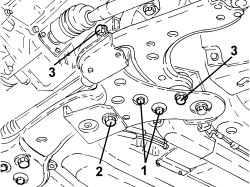
- Set up the tool for removing/refitting the suspension crossmember as described below.
1. Fit mount (1a) onto column lift (1b).
| Tool | Description | Function | Validity |
|---|---|---|---|
| 2000001700 | Mount | Suspension crossmember support |
| Tool | Description | Function | Validity |
|---|---|---|---|
| 1870835001 | Column lift | Suspension crossmember support |
2. Fit frame (2a) and secure it to the mounting with retaining pins (2b) and (2c).
| Tool | Description | Function | Validity |
|---|---|---|---|
| 2000024400 | Chassis | Suspension crossmember support |
| Tool | Description | Function | Validity |
|---|---|---|---|
| 2000024419 | Pin | Frame connection to suspension mounting |
| Tool | Description | Function | Validity |
|---|---|---|---|
| 2000024418 | Pin | Frame connection to suspension mounting |
3. Fit pins (3a), (3b), (3c) and (3d) onto frame (2a), as shown in the diagram.
| Tool | Description | Function | Validity |
|---|---|---|---|
| 2000024413 | Pin | Front suspension crossmember support |
| Tool | Description | Function | Validity |
|---|---|---|---|
| 2000024412 | Pin | Front suspension crossmember support |
| Tool | Description | Function | Validity |
|---|---|---|---|
| 2000024410 | Pin | Front suspension crossmember support |
| Tool | Description | Function | Validity |
|---|---|---|---|
| 2000024411 | Pin | Front suspension crossmember support |
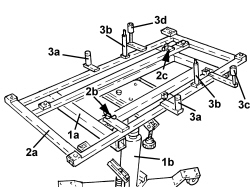
- If the above hydraulic lift is not available, use a general hydraulic lift plus the adaptor shown in the drawing, which must be made up by the workshop to allow the use of the frames mentioned above.
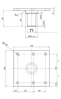
(*): Adapt the shank diameter to fit the hydraulic lift used
1. Support the suspension crossmember using the equipment prepared previously, taking care that the pins are positioned in the axle-body locating openings as illustrated.
2. Insert the split pins onto the pins to secure the crossmember to the support frame during the entire phase of removal from the vehicle.
3. Unscrew bolts (3a) securing suspension crossmember (3b) to the body, bolts (3c) securing the crossmember to the side panels and remove it from its housing.
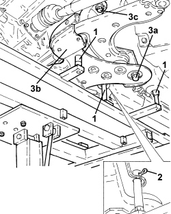
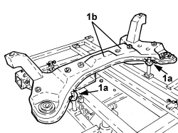
1. Disconnect split pins (1a) and remove suspension crossmember (1b) from the support frame.
Refitting
- Position the suspension crossmember on the support frame and secure it with the associated split pins.
- Place the suspension crossmember in position using the equipment used for the removal, taking care that the adaptors are positioned in the axle-body locating openings.
- Tighten the bolts securing the suspension crossmember to the body and side panels to the specified torque.
| Component | Fastening | dia | Value (daNm) | Validity |
|---|---|---|---|---|
| Front suspension crossmember to bodyshell | Bolt (to be replaced) | M12 | 9.9 ÷ 12.1 |
| Component | Fastening | dia | Value (daNm) | Validity |
|---|---|---|---|---|
| Front suspension crossmember to bodyshell | Bolt (to be replaced) | M14 | 13.5 ÷ 16.5 |
- Remove the equipment used for refitting the suspension crossmember.
- Tighten the bolts securing the wishbone to the suspension crossmember to the recommended torque.
| Component | Fastening | dia | Value (daNm) | Validity |
|---|---|---|---|---|
| Lower track control arm to front suspension crossmember | Bolt | M12 | 11.5 ÷ 12.5 |
| Component | Fastening | dia | Value (daNm) | Validity |
|---|---|---|---|---|
| Lower track control arm to front suspension crossmember | Bolt | M14 | 17.5 ÷ 19.5 |
- Tighten the bolt securing the steering box to the suspension crossmember to the recommended torque.
| Component | Fastening | dia | Value (daNm) | Validity |
|---|---|---|---|---|
| Steering box to suspension crossmember | Bolt | M12 | 7.2 ÷ 8.8 |
- Tighten the bolts securing the anti-roll bar to the suspension crossmember to the recommended torque.
| Component | Fastening | dia | Value (daNm) | Validity |
|---|---|---|---|---|
| Anti-roll bar to front suspension crossmember | Bolt | M8 | 2.3 ÷ 2.7 |
Op. 1008C32 GEARBOX LOWER REACTION ROD -R.R.
Op. 1072C16 EXHAUST MANIFOLD WITH CATALYTIC CONVERTER - R.R.
Op. 7055B54 UNDER ENGINE PROTECTION/GUARD - R.R.
Op. 4410D17 REINFORCEMENT FOR FRONT SUSPENSION CROSSMEMBER - R.R.
Op. 1072C44 EXHAUST MANIFOLD HEAT SHIELD - R+R
Op. 1048A10 AIR FILTER ASSEMBLY - R.R.
Op. 7055B66 ENGINE COMPARTMENT DUST COVER IN RIGHT FRONT WHEEL ARCH - R.R.
Op. 7055B65 ENGINE COMPARTMENT DUST COVER IN LEFT FRONT WHEEL ARCH - R.R.
Op. 4450B12 FRONT WHEELS (TWO) - R+R
Op. 4450A10 FRONT WHEEL GEOMETRY - CHECK USING OPTICAL EQUIPMENT - INCLUDES ADJUSTMENT IF NECESSARY
Removing
Op. 4450B12 FRONT WHEELS (TWO) - R+R
Op. 7055B65 ENGINE COMPARTMENT DUST COVER IN LEFT FRONT WHEEL ARCH - R.R.
Op. 7055B66 ENGINE COMPARTMENT DUST COVER IN RIGHT FRONT WHEEL ARCH - R.R.
Op. 4410D17 REINFORCEMENT FOR FRONT SUSPENSION CROSSMEMBER - R.R.
Op. 7055B54 UNDER ENGINE PROTECTION/GUARD - R.R.
Op. 1076B20 REAR EXHAUST SILENCER - R + R
- For versions with DPF only:
Op. 1080B81 PARTICULATE FILTER (D.P.F.) - R.R.
- For versions without DPF only:
Op. 1080B62 CATALYTIC CONVERTER - R + R
Op. 1076B72 INTERMEDIATE EXHAUST PIPE WITH HOSE SECTION - R+R
Op. 1008C30 POWER UNIT LOWER REACTION LINK - R.R.
Op. 1008C32 GEARBOX LOWER REACTION ROD -R.R.
The left-hand side of the suspension crossmember is shown below; proceed in the same way for the right-hand side.
1. Undo the bolts securing the anti-roll bar to the suspension crossmember.
2. Undo the bolt securing the steering box to the suspension crossmember.
3. Undo the bolts securing the wishbone to the suspension crossmember.
- Set up the tool for removing/refitting the suspension crossmember as described below.
1. Fit mount (1a) onto column lift (1b).
| Tool | Description | Function | Validity |
|---|---|---|---|
| 2000001700 | Mount | Suspension crossmember support |
| Tool | Description | Function | Validity |
|---|---|---|---|
| 1870835001 | Column lift | Suspension crossmember support |
2. Fit frame (2a) and secure it to the mounting with retaining pins (2b) and (2c).
| Tool | Description | Function | Validity |
|---|---|---|---|
| 2000024400 | Chassis | Suspension crossmember support |
| Tool | Description | Function | Validity |
|---|---|---|---|
| 2000024419 | Pin | Frame connection to suspension mounting |
| Tool | Description | Function | Validity |
|---|---|---|---|
| 2000024418 | Pin | Frame connection to suspension mounting |
3. Fit pins (3a), (3b), (3c) and (3d) onto frame (2a), as shown in the diagram.
| Tool | Description | Function | Validity |
|---|---|---|---|
| 2000024413 | Pin | Front suspension crossmember support |
| Tool | Description | Function | Validity |
|---|---|---|---|
| 2000024412 | Pin | Front suspension crossmember support |
| Tool | Description | Function | Validity |
|---|---|---|---|
| 2000024410 | Pin | Front suspension crossmember support |
| Tool | Description | Function | Validity |
|---|---|---|---|
| 2000024411 | Pin | Front suspension crossmember support |
- If the above hydraulic lift is not available, use a general hydraulic lift plus the adaptor shown in the drawing, which must be made up by the workshop to allow the use of the frames mentioned above.
(*): Adapt the shank diameter to fit the hydraulic lift used
1. Support the suspension crossmember using the equipment prepared previously, taking care that the pins are positioned in the axle-body locating openings as illustrated.
2. Insert the split pins onto the pins to secure the crossmember to the support frame during the entire phase of removal from the vehicle.
3. Unscrew bolts (3a) securing suspension crossmember (3b) to the body, bolts (3c) securing the crossmember to the side panels and remove it from its housing.
1. Disconnect split pins (1a) and remove suspension crossmember (1b) from the support frame.
Refitting
- Position the suspension crossmember on the support frame and secure it with the associated split pins.
- Place the suspension crossmember in position using the equipment used for the removal, taking care that the adaptors are positioned in the axle-body locating openings.
- Tighten the bolts securing the suspension crossmember to the body and side panels to the specified torque.
| Component | Fastening | dia | Value (daNm) | Validity |
|---|---|---|---|---|
| Front suspension crossmember to bodyshell | Bolt (to be replaced) | M12 | 9.9 ÷ 12.1 |
| Component | Fastening | dia | Value (daNm) | Validity |
|---|---|---|---|---|
| Front suspension crossmember to bodyshell | Bolt (to be replaced) | M14 | 13.5 ÷ 16.5 |
- Remove the equipment used for refitting the suspension crossmember.
- Tighten the bolts securing the wishbone to the suspension crossmember to the recommended torque.
| Component | Fastening | dia | Value (daNm) | Validity |
|---|---|---|---|---|
| Lower track control arm to front suspension crossmember | Bolt | M12 | 11.5 ÷ 12.5 |
| Component | Fastening | dia | Value (daNm) | Validity |
|---|---|---|---|---|
| Lower track control arm to front suspension crossmember | Bolt | M14 | 17.5 ÷ 19.5 |
- Tighten the bolt securing the steering box to the suspension crossmember to the recommended torque.
| Component | Fastening | dia | Value (daNm) | Validity |
|---|---|---|---|---|
| Steering box to suspension crossmember | Bolt | M12 | 7.2 ÷ 8.8 |
- Tighten the bolts securing the anti-roll bar to the suspension crossmember to the recommended torque.
| Component | Fastening | dia | Value (daNm) | Validity |
|---|---|---|---|---|
| Anti-roll bar to front suspension crossmember | Bolt | M8 | 2.3 ÷ 2.7 |
Op. 1008C32 GEARBOX LOWER REACTION ROD -R.R.
Op. 1008C30 POWER UNIT LOWER REACTION LINK - R.R.
Op. 1076B72 INTERMEDIATE EXHAUST PIPE WITH HOSE SECTION - R+R
- For versions with DPF only:
Op. 1080B81 PARTICULATE FILTER (D.P.F.) - R.R.
- For versions without DPF only:
Op. 1080B62 CATALYTIC CONVERTER - R + R
Op. 1076B20 REAR EXHAUST SILENCER - R + R
Op. 7055B54 UNDER ENGINE PROTECTION/GUARD - R.R.
Op. 4410D17 REINFORCEMENT FOR FRONT SUSPENSION CROSSMEMBER - R.R.
Op. 7055B66 ENGINE COMPARTMENT DUST COVER IN RIGHT FRONT WHEEL ARCH - R.R.
Op. 7055B65 ENGINE COMPARTMENT DUST COVER IN LEFT FRONT WHEEL ARCH - R.R.
Op. 4450B12 FRONT WHEELS (TWO) - R+R
Op. 4450A10 FRONT WHEEL GEOMETRY - CHECK USING OPTICAL EQUIPMENT - INCLUDES ADJUSTMENT IF NECESSARY
Parts & tools for this job For 2007 Fiat Bravo
- TOOLCoil spring compressorSearch: coil spring compressor
- TOOLBall joint separatorSearch: ball joint separator
- PARTFront shock absorbersSearch: Fiat Bravo 2007 front shock absorbers
Links open Amazon search results in a new tab. As an Amazon Associate I earn from qualifying purchases.