
Injectors
- Make
- Fiat
- Model
- Bravo /Brava (182) Factory Service Manual
- Year
- 1995–2001
- Section
- Fuel feed system (2000 range, 1910 JTD) › Injectors
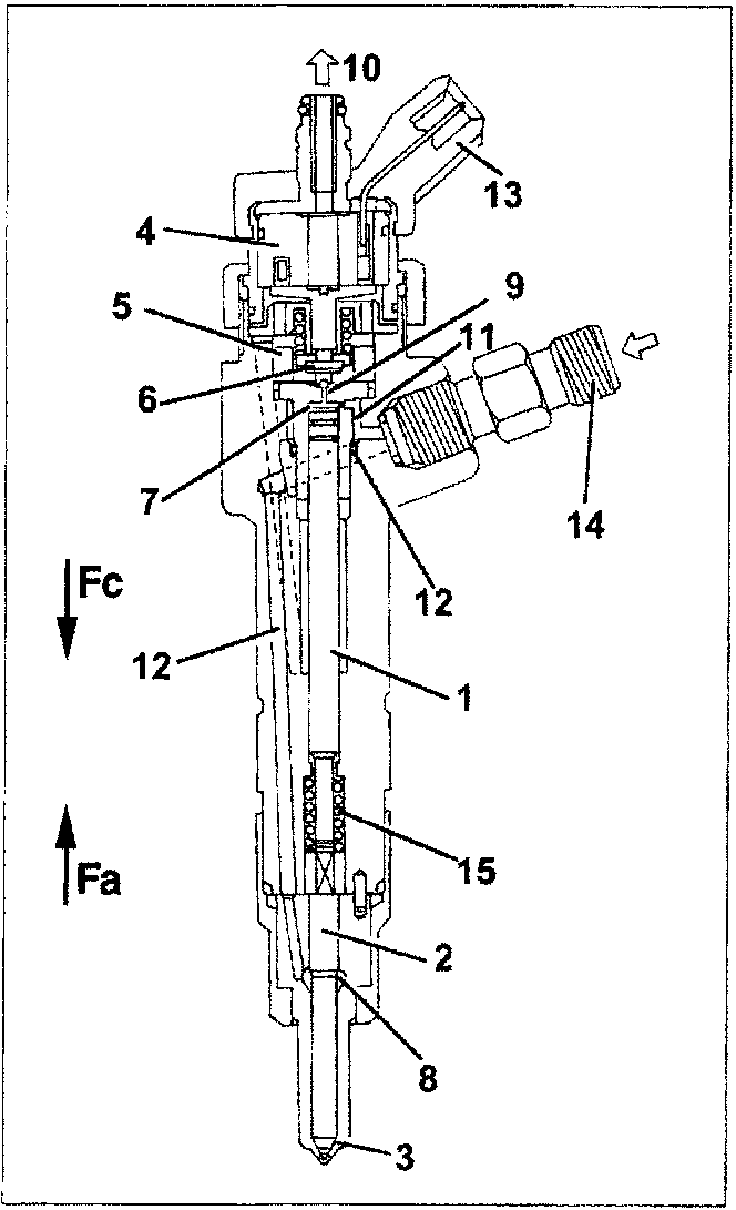
- Pressure rod
- Pin
- Nozzle
- Coil
- Pilot valve
- Ball plunger
- Control area
- Supply volume
- Control volume
- Fuel outlet connector (low pressure)
- Control port
- Supply port
- Electrical connection
- Fuel input connector (high pressure)
- Spring
INJECTORS
The injectors are fitted to the cylinder head and are electromagnetic in type. They are controlled directly by the injection control unit.
The injectors come with a high-pressure supply port and a recirculation pipe at environmental pressure; The supply port is connected to a delivery manifold (rail) with pipes designed to withstand the high service pressures.
The injector can be divided into two parts:
- Actuator/spray made up of a pressure rod (1), pin (2) and nozzle (3);
- control solenoid made up of coil (4) and pilot valve (5).
Operation
Injector operation may be divided into three stages:
1. rest position
Coil (4) is deactivated and plunger (6) is in closed position to prevent fuel entering the cylinder: Fc > Fa where Fc is the force generated by pressure acting on the control area (7) of pressure rod (1) and Fa is the force due to the pressure acting on supply volume (8).
2. Start of injection
Coil (4) is excited and causes plunger (6) to rise. Fuel flows from control volume (9) to the return manifold to bring about a pressure drop in control area (7). Simultaneously, line pressure through supply port (12) exercises a force Fa > Fc on supply volume (8) to cause pin (2) to rise and thus allow fuel into the cylinders.
3. end of injection
Coil (4) is deactivated and causes plunger (6) to return to closed position. The resulting balance of forces makes pin (2) return to rest position and injection therefore ends.
Parts & tools for this job For 1995 Fiat Bravo
- PARTFuel filterSearch: Fiat Bravo 1995 fuel filter
- TOOLFuel pressure test kitSearch: fuel pressure test kit
- TOOLFuel line disconnect toolSearch: fuel line disconnect tool
Links open Amazon search results in a new tab. As an Amazon Associate I earn from qualifying purchases.