
Test
- Make
- Fiat
- Model
- Bravo /Brava (182) Factory Service Manual
- Year
- 1995–2001
- Section
- Fuel feed system (2000 range, 1910 JTD) › Test
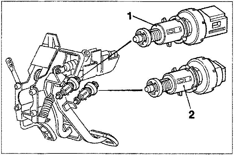
TEST
A switch (1) on the brake pedal controls the car brake lights; the same switch sends a signal to pin 59 of the injection control unit
The control unit uses the "brake pedal depressed" signal to:
- detect a situation of over-run;
- check the plausibility of the signal from the accelerator potentiometer
CLUTCH PEDAL SWITCH
A switch (2) on the clutch pedal is connected to pin 61 of the injection control unit. The injection control unit uses the "brake pedal operated" signal to distinguish gear engaged and gear shift conditions.
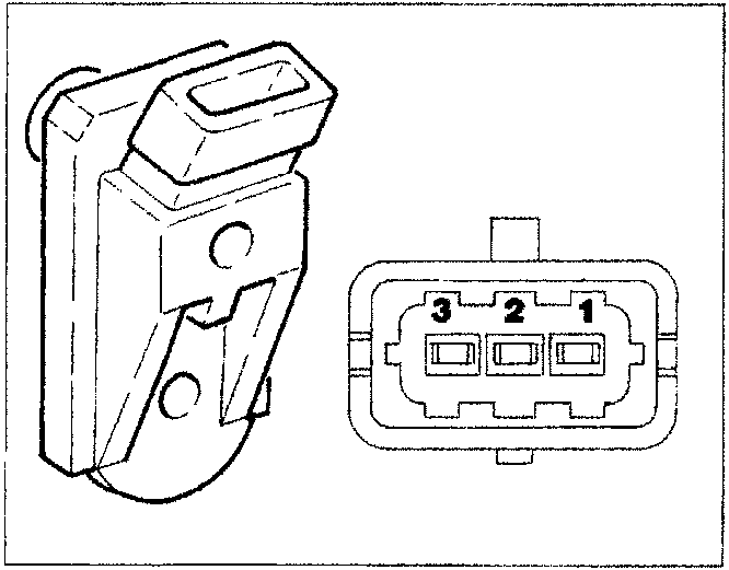
PRESSURE RELIEF SENSOR
The sensor is fitted to the intake manifold and the signal sent to the injection control unit is used to:
- adjust injection pressure;
- adjust injection duration.
The figure alongside shows the sensor and electrical connector with the following pin-out:
- pressure signal
- Permissible
- Fuel feed system
ATMOSPHERIC PRESSURE SENSOR
The atmospheric pressure signal is built into the injection control unit. It is responsible for measuring atmospheric pressure in order to correct measured air flow and reference air flow values to control the EGR function.
Parts & tools for this job For 1995 Fiat Bravo
- PARTEngine gasket setSearch: Fiat Bravo 1995 engine gasket set
- TOOLTorque wrenchSearch: 3/8 inch torque wrench
- TOOLFeeler gauge setSearch: feeler gauge set
Links open Amazon search results in a new tab. As an Amazon Associate I earn from qualifying purchases.