
Turbocharger
- Make
- Fiat
- Model
- Bravo /Brava (182) Factory Service Manual
- Year
- 1995–2001
- Section
- Fuel feed system (2000 range, 1910 JTD) › Turbocharger
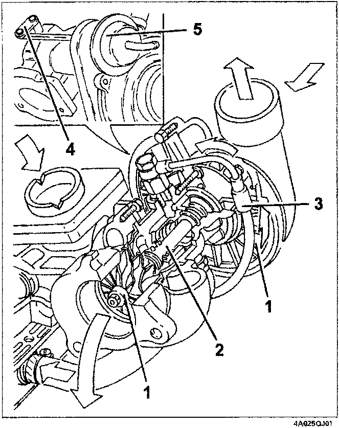
TURBOCHARGER
This consists essentially of two impellers (1) fitted to the same shaft (2), which rotates on floating bearings lubricate via a branch (3) of the engine lubrication system.
The oil used dissipates a proportion of the great quantity of heat given up by the exhaust gas to the turbine.
The turbocharger is fitted with a wastegate (4) controlled by a pneumatic actuator (5), which partially restricts the passage of exhaust gases to the turbine according to engine power/torque requirements.
The pneumatic actuators is controlled by the engine control unit via a solenoid.
- Impellers
- Shaft
- Lubrication
- Wastegate
- Actuator
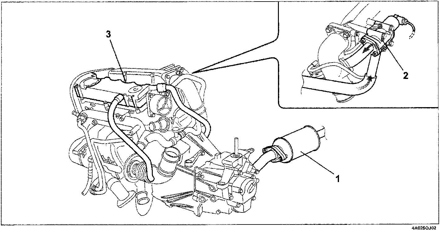
EMISSION CONTROL DEVICES
The car is equipped with devices designed to reduce polluting emissions in accordance with Euro 3 requirements:
- Oxidising catalytic converter (1)
- Exhaust gas recirculation circuit (EGR) (2)
- Crankcase blow-by vapour recirculation circuit (3).
Parts & tools for this job For 1995 Fiat Bravo
- PARTEngine gasket setSearch: Fiat Bravo 1995 engine gasket set
- TOOLTorque wrenchSearch: 3/8 inch torque wrench
- TOOLFeeler gauge setSearch: feeler gauge set
Links open Amazon search results in a new tab. As an Amazon Associate I earn from qualifying purchases.