
Air intake circuit diagram
- Make
- Fiat
- Model
- Bravo /Brava (182) Factory Service Manual
- Year
- 1995–2001
- Section
- Fuel system (1370 12v) › Air intake circuit diagram
‹ Prev Diagram showing input/output between ECU and sensors/actuators of the Bosch Monomotronic SPI injection-ignition systemNext › Fuel supply circuit diagram
10 EngineAir intake circuit diagram
AIR INTAKE CIRCUIT DIAGRAM
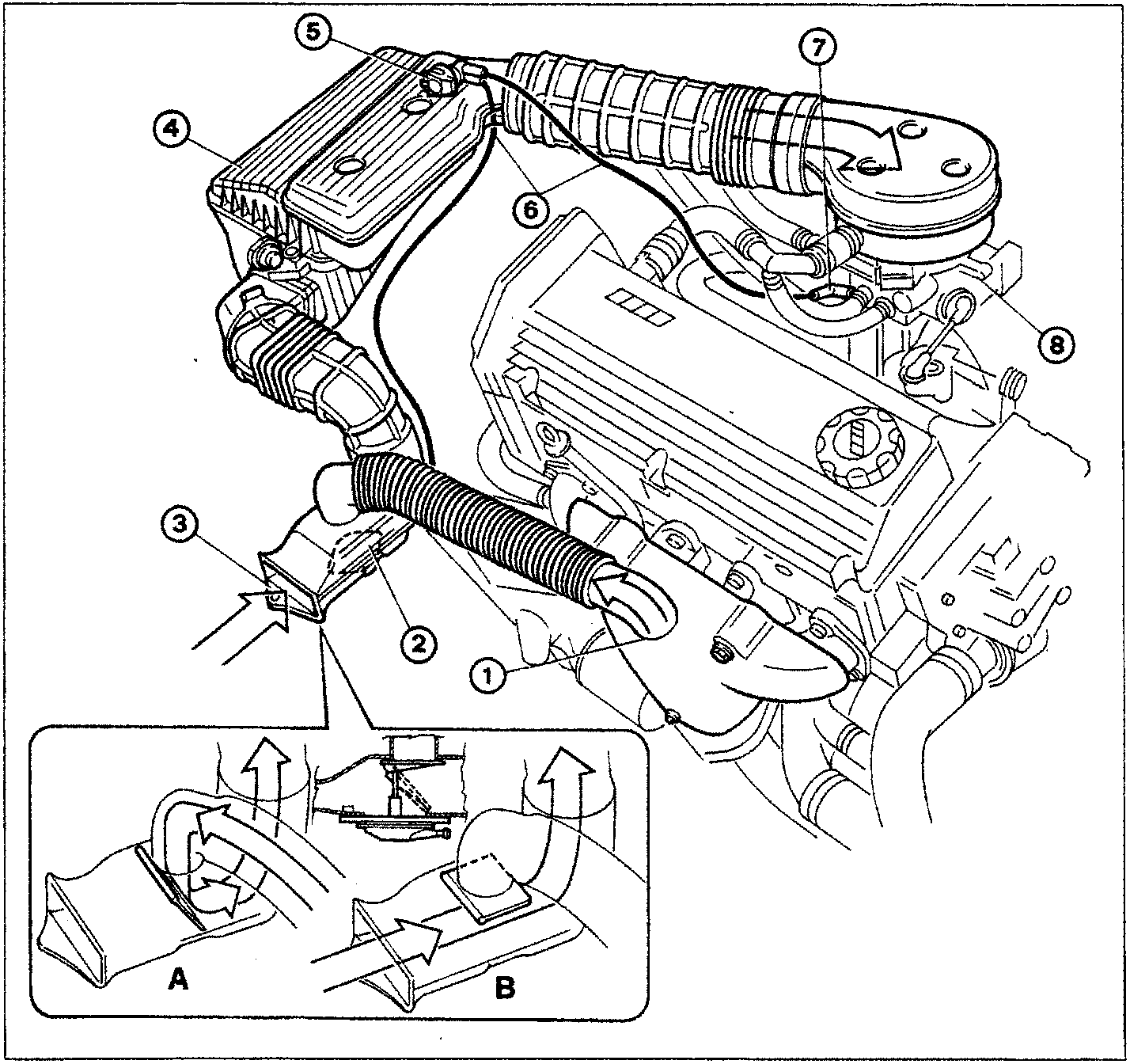
- Warm air intake on exhaust manifold
- Actuator for warm/cold air deflector
- Cold air intake fitting
- Air cleaner
- Thermostatic valve
- Vacuum ducts
- Vacuum socket
- Throttle case
The air intake circuits comprises various components which ensure sufficient air is carried to the engine under different service conditions.
The intake of warm or cold air is selected by deflector (2) which may or may not be affected by the vacuum in the intake manifold according to position of thermostatic valve (5).
More specifically, when intake air temperature exceeds 9°C, thermostatic valve (5) stays closed and does not allow the vacuum to reach actuator (2) (position B).
Viceversa, when intake air temperature drops below 9°C, the thermostatic valve (5) opens to allow a vacuum through to actuator (2) (position A).
‹ Prev Diagram showing input/output between ECU and sensors/actuators of the Bosch Monomotronic SPI injection-ignition systemNext › Fuel supply circuit diagram
Parts & tools for this job For 1995 Fiat Bravo
- TOOLDigital multimeterSearch: automotive digital multimeter
- PARTAssorted fuse kitSearch: car fuse assortment kit
- TOOLWire crimper and connector kitSearch: wire crimper connector kit
Links open Amazon search results in a new tab. As an Amazon Associate I earn from qualifying purchases.