
Components of injection-ignition system
- Make
- Fiat
- Model
- Bravo /Brava (182) Factory Service Manual
- Year
- 1995–2001
- Section
- Fuel system (1370 12v) › Components of injection-ignition system
COMPONENTS OF INJECTION-IGNITION SYSTEM
The injection-ignition system consists mainly of wiring, an electronic control unit (i.e. ECU) and the following sensors and actuators:
Sensors
- Speedometer sensor
- Rpm and TDC sensor.
- Knock sensor
- Coolant temperature sensor
- Throttle position sensor
- Intake air temperature sensor
- Lambda probe sensor
Actuators
- Engine idle speed actuator
- Fuel vapour cut-off solenoid
- Electric fuel pump
- Injector
- Ignition coil
- Spark plugs
INJECTION-IGNITION SYSTEM WIRING
The various system components are connected by a single wiring system fitted with connectors of various types. These are grouped in special ducts fitted to the engine (prewiring).
INJECTION-IGNITION ECU (0.261.203.868)
The ECU analyses data on engine service conditions transmitted by the sensors. Input signals from peripheral sensors are processes and injector/ignition timing pulses are governed with the aid of programmed typical curves.
The ECU is connected to the system by means of a 35 pin connector and protected by false polarities and circuit-breakers.
The ECU is able to detect when sensors are not working efficiently and replace incorrect or missing data with data taken from certain areas of its memory in order to ensure engine operation even under emergency conditions. It is also equipped with a full SELF-DIAGNOSTIC strategy for both input and output sensors. It also contains a special memory able to record any faults received during testing.
When a Fiat/Lancia TESTER is connected to the system it is therefore possible to test or display any errors stored in the memory.
Another important feature of the ECU is self-adaption. This function allows the system to recognise various changes (ranging from atmospheric changes to changes due to component wear) which could impair efficient engine operation and adjust to them by implementing appropriate strategies.
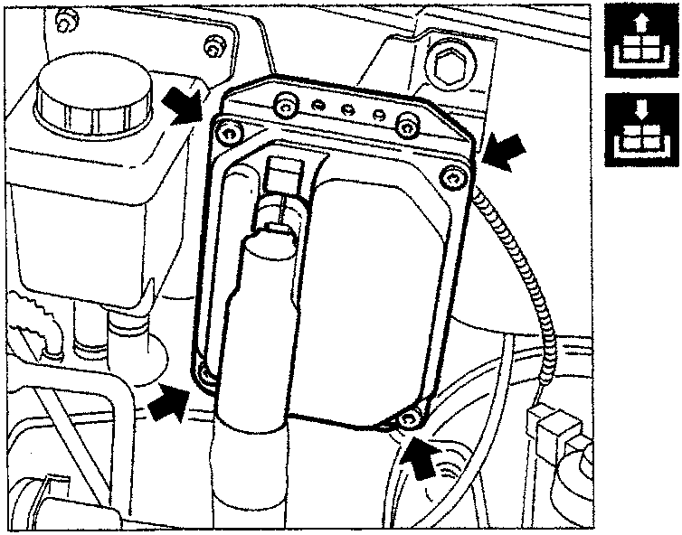
Removing-refitting control unit
Disconnect electrical connection. Undo retaining nuts and remove ECU.
It is absolutely prohibited to exchange injection control units between different vehicles in order to check their efficiency.
Before replacing an ECU as a result of testing, ensure it is really faulty because when a new ECU is activated, the secret Fiat CODE system code is memorised and this makes the unit completely unusable on other vehicles.
Parts & tools for this job For 1995 Fiat Bravo
- PARTSpark plugsSearch: Fiat Bravo 1995 spark plugs
- TOOLSpark plug socketSearch: spark plug socket
- TOOLSpark plug gap toolSearch: spark plug gap tool
Links open Amazon search results in a new tab. As an Amazon Associate I earn from qualifying purchases.