
Blow-by gas recirculation diagram
- Make
- Fiat
- Model
- Bravo /Brava (182) Factory Service Manual
- Year
- 1995–2001
- Section
- Fuel system (1370 12v) › Blow-by gas recirculation diagram
BLOW-BY GAS RECIRCULATION DIAGRAM
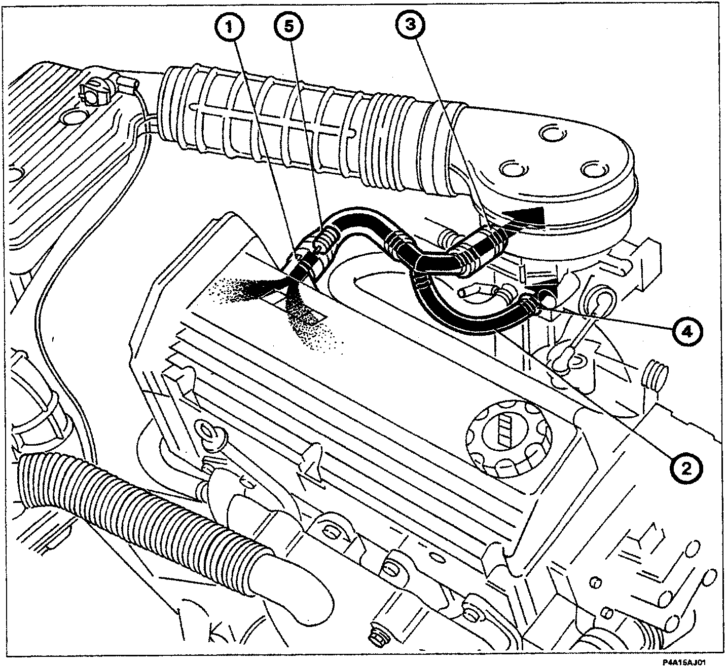
The system controls emission, from the engine block, of vent gases made up of air-fuel mixtures, burnt gases which leak through piston rings and lubricant oil vapours by recirculating them to the intake.
Gases emerge from outlet (1), which contains a flame trap (5) designed to prevent combustion caused by flame flashing back from the butterfly valve case.
With the accelerator throttle open, gases are taken in upstream of the throttle through intake (3) located on the air shroud to the butterfly valve case.
With the throttle closed (engine idling), the vacuum in the intake manifold takes up gas (in limited quantities) directly through the pipe (2) and calibrated hole (4).
Parts & tools for this job For 1995 Fiat Bravo
- PARTFuel filterSearch: Fiat Bravo 1995 fuel filter
- TOOLFuel pressure test kitSearch: fuel pressure test kit
- TOOLFuel line disconnect toolSearch: fuel line disconnect tool
Links open Amazon search results in a new tab. As an Amazon Associate I earn from qualifying purchases.