
Injection system fuses and relays
- Make
- Fiat
- Model
- Bravo /Brava (182) Factory Service Manual
- Year
- 1995–2001
- Section
- Fuel system (1370 12v) › Injection system fuses and relays
‹ Prev Location of injection-ignition system components in engine bayNext › Components of injection-ignition system
10 EngineInjection system fuses and relays
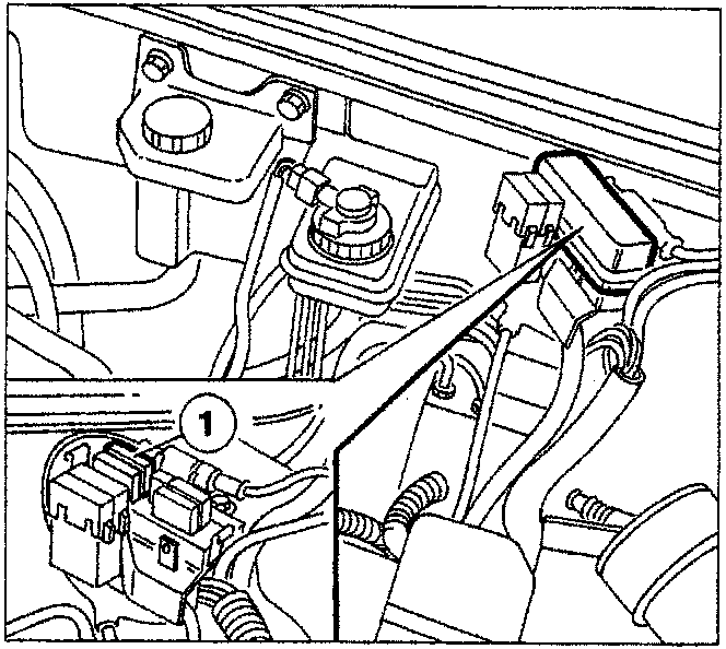
INJECTION SYSTEM FUSES AND RELAYS
General system protection fuse
The general fuse (EFI-30A) protecting the injection-ignition system (1) is housed inside a container; to gain access to the fuse, undo side clips and lift lid.
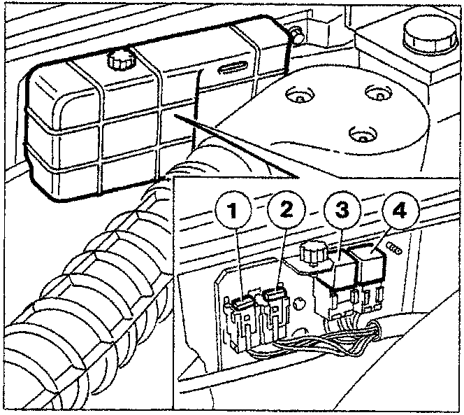
Fuses and relays
The following components are housed on a bracket located against the rear wall of the engine bay:
- 10A fuse for fuel pump
- 10A injection-ignition system fuse
- Injection-ignition system relay
- Fuel pump relay
Unscrew ring nut and remove cover to gain access to the above components.
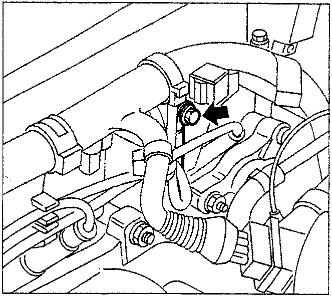
EARTH POINT
The earth of the injection-ignition system is fixed at the right rear of the engine, close to the first cylinder spark plug.
‹ Prev Location of injection-ignition system components in engine bayNext › Components of injection-ignition system
Parts & tools for this job For 1995 Fiat Bravo
- TOOLDigital multimeterSearch: automotive digital multimeter
- PARTAssorted fuse kitSearch: car fuse assortment kit
- TOOLWire crimper and connector kitSearch: wire crimper connector kit
Links open Amazon search results in a new tab. As an Amazon Associate I earn from qualifying purchases.