
Stalk unit assembly - r+r
- Make
- Fiat
- Model
- Croma Factory Service Manual
- Year
- 2005–2010
- Section
- Warning and manoeuvring indicators › Stalk unit assembly - r+r
STALK UNIT ASSEMBLY - R+R
Before working on the air bag system, it is essential to perform the following preliminary operations.
- Turn the ignition key to the OFF position and extract it.
- Disconnect the battery leads and insulate them.
- Wait for 10 minutes before continuing.
| Description | Connector | |
|---|---|---|
| BATTERY | See A001 BATTERY |
FOLLOW ALL THE RECOMMENDED SAFETY INSTRUCTIONS
Removing
Op. 5580C18 AIR BAG MODULE - R+R
Op. 4110A10 STEERING WHEEL - R+R FOR REPLACEMENT OR CHECKS
Op. 7040A26 STEERING COLUMN TRIM - R+R
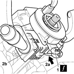
1. Disconnect the electrical connection for clock spring.
| Description | Connector | |
|---|---|---|
| 1 | CLOCK SPRING COUPLING | See D047 CLOCK SPRING COUPLING |
2. Working from below, loosen the bolt of anchorage collar (2a) and withdraw stalk unit (2b) from the steering column.
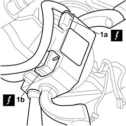
1. Release the anchorages and disconnect connections (1a) and (1b).
| Description | Connector | |
|---|---|---|
| 1a | ABS COUPLING | See D005 ABS COUPLING |
| Description | Connector | |
|---|---|---|
| 1b | ABS COUPLING | See D005 ABS COUPLING |
| Description | Connector | |
|---|---|---|
| 1b | ABS COUPLING | See D005 ABS COUPLING |
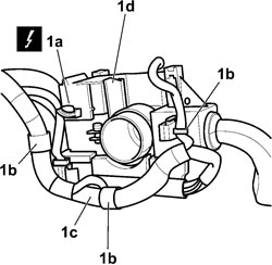
- Turn the stalk unit through 180°.
1. Disconnect the electrical connection of the Cruise Control device on the rear of the stalk unit, release wiring harness (1c) from anchorages (1b) and remove the stalk unit (1d).
| Description | Connector | |
|---|---|---|
| 1a | STEERING COLUMN SWITCH UNIT | See H005 STEERING COLUMN SWITCH UNIT |
Refitting
Parts supplies new stalk units complete with steering angle sensor. The steering angle sensor electrical connector must be secured so that it does not cause noise while the vehicle is in motion.
- Connect the electrical connections to the stalk unit complete with clock spring.
| Description | Connector | |
|---|---|---|
| CLOCK SPRING COUPLING | See D047 CLOCK SPRING COUPLING |
| Description | Connector | |
|---|---|---|
| ABS COUPLING | See D005 ABS COUPLING |
| Description | Connector | |
|---|---|---|
| STEERING COLUMN SWITCH UNIT | See H005 STEERING COLUMN SWITCH UNIT |
- Engage the wiring harness in the anchorages
- Position the stalk unit complete with clock spring on the steering column.
Op. 7040A26 STEERING COLUMN TRIM - R+R
Before fitting the steering wheel in its seat, split the red key on the stalk unit that ensures its protection.
Op. 5580C18 AIR BAG MODULE - R+R
- Connect the battery terminals.
| Description | Connector | |
|---|---|---|
| BATTERY | See A001 BATTERY |
Parts & tools for this job For 2005 Fiat Croma
- TOOLDigital multimeterSearch: automotive digital multimeter
- PARTAssorted fuse kitSearch: car fuse assortment kit
- TOOLWire crimper and connector kitSearch: wire crimper connector kit
Links open Amazon search results in a new tab. As an Amazon Associate I earn from qualifying purchases.