
Front side panel (level 1)
- Make
- Fiat
- Model
- Idea Factory Service Manual
- Year
- 2003–2012
- Section
- Removing refitting › Front side panel (level 1)
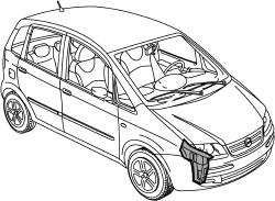
Front side panel (level 1)
Removing
- 7210A15 R.R. HEADLAMP HOUSING/FRONT WING CROSSMEMBER
- 7210A16 R.R. WING LOWER CROSSMEMBER
Check if any of the connected parts are deformed by checking body alignment dimensions. Use appropriate measurement tools (reference rigs, templates or gauges).
Straighten the body if necessary.
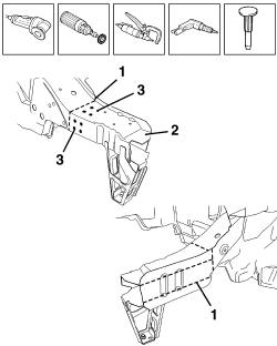
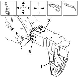
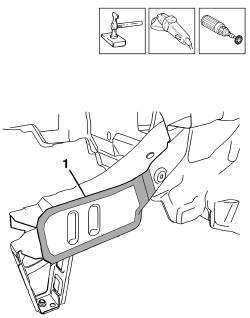
1. Use a circular saw to follow the cutting lines shown in the figure. Take great care not to damage the reinforcement underneath.
2. Remove the side panel.
Use a rotary brush to remove paint to gain access to the weld spots.
3. Use a chamfering machine to remove the weld spots shown in the figure.
Drill out any weld spots not accessible to the chamfering machine.
Use a chisel and mallet to remove spots drilled previously.
Trim the cut edges from the car.
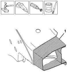
Straighten the car edges using a mallet and profiled stake.
Use a grinding wheel to remove the spot weld residues.
Use a rotary brush to clean treated areas.
1. Apply the electroweldable paint finish.
Refitting
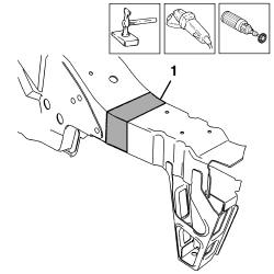
1. Take the measurements carefully and cut the replacement innner panel as required keeping a section of panel for the overlap.
2. Use a grinding wheel to remove the corrosion-proofing from around the inner and outer edges of the replacement inner panel.
3. Drill out the holes indicated.
Apply electric weld paint finish to the edges to be welded.
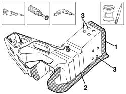
1. Correctly position the inner panel on the vehicle and secure it using self-locking clamps.
Check the alignment and ensure the surrounding gaps are even.
2. Use a circular saw to trim the panel along the join line to remove any excess parts.
3. Use a MIG welder to fill the holes made previously.
4. Use the MIG welder to seam weld the join profile.
Correct any deformations in the panel using a profiled stake and mallet.
Use a grinding wheel to level the welds
1. Use a rotary brush to clean the newly-welded areas.
1. Take the measurements carefully and cut the replacement outer panel as required keeping a section of panel for the overlap.
2. Use a grinding wheel to remove the corrosion-proofing from around the inner and outer edges of the replacement panel.
Apply electric weld paint finish to the edges to be welded.
1. Correctly position the outer panel on the vehicle and secure it using self-locking clamps.
Check the alignment and ensure the surrounding gaps are even.
2. Use a circular saw to trim the panel along the join line to remove any excess parts.
3. Use a spot welder to weld the areas shown in the figure.
4. Use the MIG welder to seam weld the join profile.
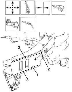
Correct any deformations in the panel using a profiled stake and mallet.
Use a grinding wheel to level the welds
1. Use a rotary brush to clean the newly-welded areas.
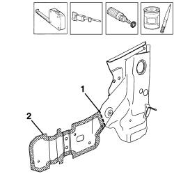
1. For the left panel only. Use a grinding wheel to remove the corrosion-proofing from around the inner and outer edges of the replacement battery drip tray mounting bracket.
Apply electric weld paint finish to the edges to be welded.
2. Drill out the holes indicated.
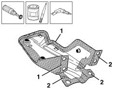
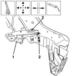
1. Position the battery drip tray mounting bracket correctly on the vehicle and secure it using self-locking clamps.
Check the alignment and ensure the surrounding gaps are even.
2. Use a MIG welder to fill the holes made previously.
Correct any deformations in the panel using a profiled stake and mallet.
Use a grinding wheel to level the welds
Use a rotary brush to clean the newly-welded areas.
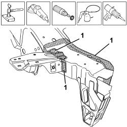
1. Apply rust-proofing to newly-welded areas.
Seal the joint lines between the part and the car.
Parts & tools for this job For 2003 Fiat Idea
- TOOLTrim removal tool kitSearch: trim removal tool kit
- PARTTouch-up paintSearch: Fiat touch up paint
- PARTPanel clip assortmentSearch: Fiat panel clips assortment
Links open Amazon search results in a new tab. As an Amazon Associate I earn from qualifying purchases.