
Clutch Mechanism – K1.8 Engines
- Make
- Land Rover
- Model
- Freelander System Description and Operation (UK)
- Section
- Description and operation › Clutch Mechanism – K1.8 Engines
Clutch Mechanism – K1.8 Engines
The clutch mechanism comprises a flywheel, clutch driven plate, clutch cover assembly, release lever, release fork and a release bearing. The clutch mechanism is fully enclosed at the end of the engine by a bell housing formed by the gearbox casing.
The spindle of the release lever is located through machined bores in the gearbox casing. The release fork fits on the release lever spindle and is secured to the spindle with a bolt and spring washer. An oil seal is located at the outer face of the gearbox casing and seals against the release lever spindle preventing the ingress of dirt and moisture.
A release bearing is operated by the release fork. The bearing has two lugs which clip onto the arms of the release fork.
The flywheel is bolted to the flange of the engine crankshaft with six bolts. A dowel ensures that the flywheel is correctly located. A ring gear is located on the outside diameter of the flywheel and is seated against a flange. The ring gear is an interference fit on the flywheel and is installed by heating the ring gear and cooling the flywheel. The ring gear is a serviceable item and can be replaced if damaged or worn.
The operating face of the flywheel is machined to provide a smooth surface for the clutch driven plate to engage on. Three dowels are fitted to the outer diameter of the flywheel and provide for the location of the clutch cover assembly. Six threaded holes provide for the attachment of the clutch cover assembly. The flywheel is balanced to ensure that it does not produce vibration when rotating.
Clutch Cover Assembly
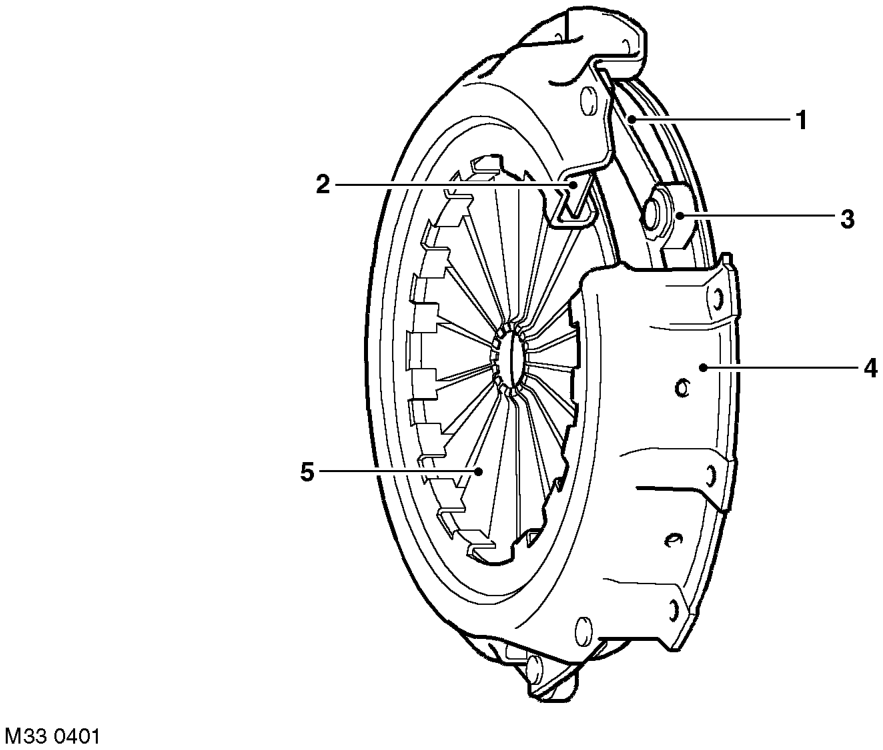
1 Drive straps 2 Fulcrum rings 3 Pressure plate
4 Cover 5 Diaphragm spring
The clutch cover assembly comprises a diaphragm spring, pressure plate and cover. The clutch cover assembly is mounted on and rotates with the flywheel. Three dowels locate the cover and six bolts secure it to the flywheel.
The 228 mm (9.0 in) diameter pressure plate is forged from cast iron and machined to provide a smooth surface for the drive plate to engage on. Three lugs on the outer diameter of the pressure plate connect it via drive straps to the cover. The drive straps have three tempered steel leaves and pull the pressure plate away from the drive plate when the clutch pedal is depressed. The cover is made from pressed steel.
Parts & tools for this job For Land Rover Freelander
- PARTEngine gasket setSearch: Land Rover Freelander engine gasket set
- TOOLTorque wrenchSearch: 3/8 inch torque wrench
- TOOLFeeler gauge setSearch: feeler gauge set
Links open Amazon search results in a new tab. As an Amazon Associate I earn from qualifying purchases.