
Ignition and shift interlock – circuit diagram
- Make
- Land Rover
- Model
- Range Rover Classic Electrical Troubleshooting Manual
- Year
- 1995
- Section
- Circuit diagram › Ignition and shift interlock – circuit diagram
Ignition and shift interlockIgnition and shift interlock – circuit diagram
IGNITION AND SHIFT INTERLOCK – CIRCUIT DIAGRAM
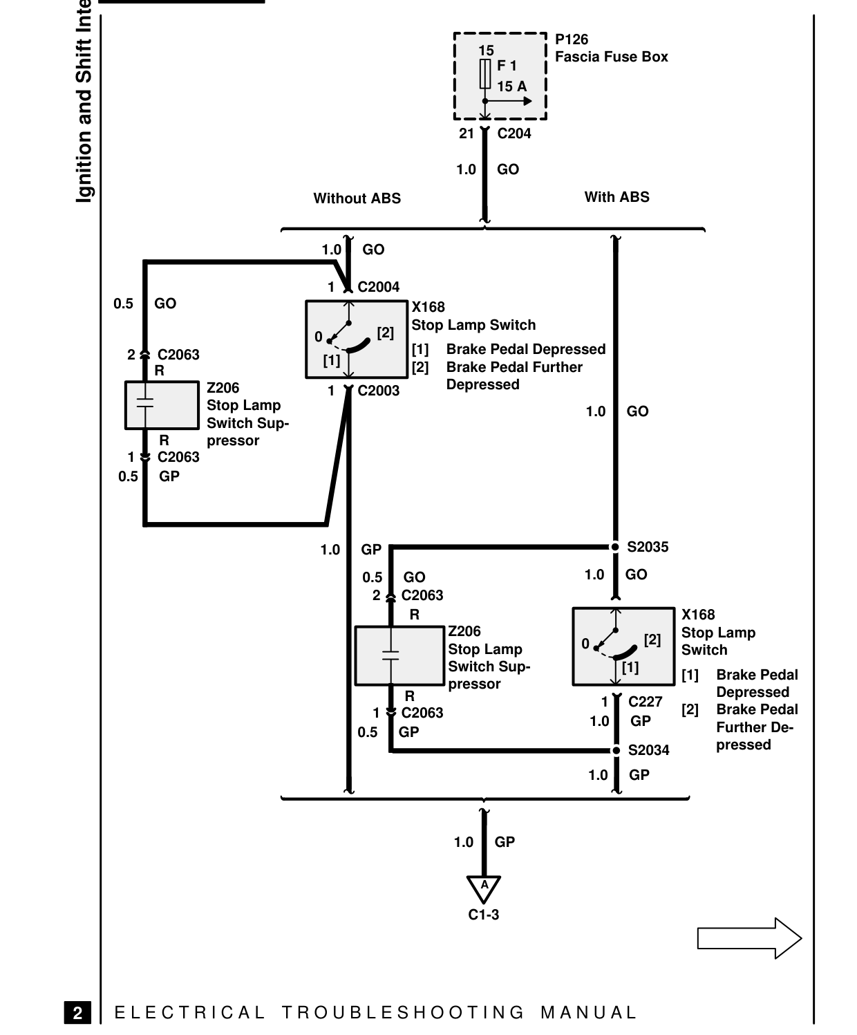
Ignition and Shift Interlock Without ABS
1.0 GO
1 C2004 0.5 GO
[2] 0 2 C2063 [1] R Z206 1 C2003 Stop Lamp Switch Sup- pressor R 1 C2063 0.5 GP
1.0 GP 0.5 2
1 0.5 GP
E L E C T R I C A L T R O U B L E S H O O T I N G
2
P126 15 Fascia Fuse Box F 1 15 A
21 C204
1.0 GO With ABS
X168 Stop Lamp Switch [1] Brake Pedal Depressed [2] Brake Pedal Further Depressed 1.0 GO
S2035 1.0 GO GO C2063 2 C227 R X168 Z206 Stop Lamp [2] 0 Stop Lamp Switch Switch Sup- [1] [1] Brake Pedal pressor Depressed R 1 C227 [2] Brake Pedal C2063 1.0 GP Further De- pressed S2034 1.0 GP
1.0 GP
A
C1-3
M A N U A L
Parts & tools for this job For 1995 Land Rover Range Rover
- TOOLDigital multimeterSearch: automotive digital multimeter
- PARTAssorted fuse kitSearch: car fuse assortment kit
- TOOLWire crimper and connector kitSearch: wire crimper connector kit
Links open Amazon search results in a new tab. As an Amazon Associate I earn from qualifying purchases.