
1.4.0.3. Cylinder Head — Assembly
- Make
- Peugeot
- Model
- J5 Pocket Mechanic, 1.8 and 2.0 petrol
- Year
- 1987–1994
- Section
- Servicing and overhaul › 1.4.0.3. Cylinder Head — Assembly
screw the plate. Carefully withdraw the shaft wityhout hitting with the cams against the bearing shells.
Place the camshaft with the two outer bearing journals in- to “V” blocks, as shown in Fig. 1.57 or clamp the shaft into a lathe and apply a dial gauge to the centre. Slowly rotate the camshaft and read off the indication of the dial gauge. If the run-out of the shaft is more than 0.01 mm, replace the shaft, as it is bent.
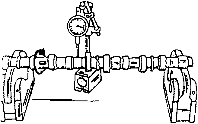
Fig. 1.57. — Checking a camshaft for run-out.
Check the bearing journals for visible wear. Obvious wear requires the replacement of the camshaft. Note that replacement camshafts have a different identification colour.
Check all cams for obvious wear, usually shown by shiny faces.
To measure the end float of the camshaft, fit it into the cylinder block and attach a dial gauge to the cylinder block, with the stylus resting against the end of the shaft. Move the shaft to and fro and read the dial gauge. If the reading is more than 0.14 mm, replace the keeper plate. In severe cases the thrust face of the camshaft could be worn, i.e. replace the camshaft.
1.4.0.3. Cylinder Head — Assembly
If the cylinder had has been replaced, transfer exhaust manifold, spark plugs, thermo switches, etc. from the old to the new head. Make sure all parts are clean. All sliding and rotating parts should be lubricated with oil.
- Insert the well oiled valves into the respective valve guides. If the original valves are used, fit them to the same valve guides; if the valves have been ground-in, make sure that the valve is fitted to the valve seat in which it has been ground-in.
- Assemble the valves. First place the valve spring seat over the cylinder head and push the valve stem seals over the valve stems and valve guides. Fit the valve springs and the upper valve spring cup to the valve spring and compress the spring with a valve spring compressor. When the valve stem end protrudes from the valve spring cup, insert the two valve cotter halves with a pair of pointed pliers. Slowly release the valve spring compressor, checking continuously that the cotter halves are kept in position.
- With a plastic mallet, tap against the end of all valve stems. If the valve cotter halves have not engaged properly, they will jump out. A piece of rag should be replaced over the valve stem ends — just in case.
- The remaining assembly is carried out in reverse order to the removal procedure. Adjust the valve clearance as described in Section 1.4.0.5.
- The fitting and adjustment of the drive belts for the water pump and alternator are described in Section “Cooling System”.
Parts & tools for this job For 1987 Peugeot J5
- PARTEngine gasket setSearch: Peugeot J5 1987 engine gasket set
- TOOLTorque wrenchSearch: 3/8 inch torque wrench
- TOOLFeeler gauge setSearch: feeler gauge set
Links open Amazon search results in a new tab. As an Amazon Associate I earn from qualifying purchases.