
1.4.0.4. Valve Clearance Adjustment
- Make
- Peugeot
- Model
- J5 Pocket Mechanic, 1.8 and 2.0 petrol
- Year
- 1987–1994
- Section
- Servicing and overhaul › 1.4.0.4. Valve Clearance Adjustment
Engine1.4.0.4. Valve Clearance Adjustment · page 1 of 2
sition of its elongated clamp slot. The engine will start, enabling you to adjust the ignition with the engine running.
- Fit the water pump to the cylinder head, using new rubber seals. Note the tightening torques: 8 mm nuts = 2.3 kgm, 10 mm nuts = 4.2 kgm, 10 mm bolts = 2.75 kgm.
1.4.0.4. Valve Clearance Adjustment
If the adjustment is carried out with the engine fitted, as is the case during a routine check of the valve clearances, remove certain parts to gain access to the valves. These include the cylinder head (rocker) cover, air cleaner, certain hoses, etc. Valve clearances can be adjusted by two different methods, both are described.
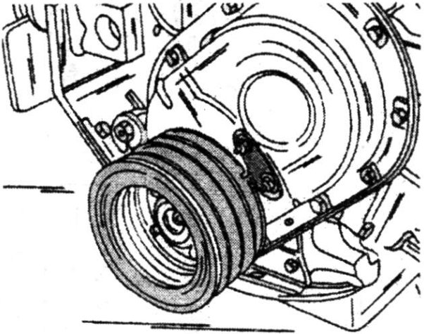
- Rotate the engine until the exhaust valve of No. 1 cylinder is full open. In this position adjust the inlet valve of No. 3 cylinder and the exhaust valve of No. 4 cylinder. To rotate the engine either apply a socket to the crankshaft pulley nut (35 mm A/F) or jack up one of the front wheels, engage the highest gear and rotate the wheel until the crankshaft is in the correct position. The spark plugs can be removed to facilitate the rotation of the crankshaft.
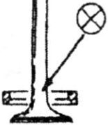
- Rotate the engine further until the next exhaust valve is fully open. Adjust the valves in accordance with Fig. 1.61. On the left you see the exhaust valves. The cam must be in the position shown when the valve is fully open. On the right you will see the valves to be adjusted.
- The valves can also be adjusted when one set of valves is fully closed. Following this method, rotate the crankshaft until the valves of No. 1 cylinder are fully closed, i.e. the cams of the two valves must be in the position shown in Fig. 1.62. This can be checked on No. 4 cylinder, where one valve should be opening and the other one closing, i.e. the valves are whats technically known “rocking”. If you now move the rocker levers of No. 1 cylinder up and down you
Parts & tools for this job For 1987 Peugeot J5
- PARTEngine gasket setSearch: Peugeot J5 1987 engine gasket set
- TOOLTorque wrenchSearch: 3/8 inch torque wrench
- TOOLFeeler gauge setSearch: feeler gauge set
Links open Amazon search results in a new tab. As an Amazon Associate I earn from qualifying purchases.