
Cylinder Head:
- Make
- Peugeot
- Model
- J5 Pocket Mechanic, 1.8 and 2.0 petrol
- Year
- 1987–1994
- Section
- Servicing and overhaul › Cylinder Head:
New valve guides always require the fitting of new valves and the valve seats must be re-cut and the valves ground into the seats.
If you fit the guides yourself, lubricate them with engine oil and press or drive them into the cylinder head until dimension “X” in Fig. 1.55 has the required value. From the illustration you will also see the inclination of the guides, i.e. the cylinder head must be supported on one side to have the respective guide in vertical position. Valve guides must be reamed after installation to the diameter given in Section 1.4.0.0. The guides of all engines have the same inner diameter. Use an adjustable reamer. The correct running clearance is automatically obtained when the guides have the correct internal diameter.
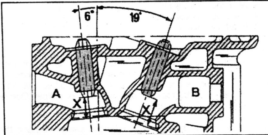
Attention: The valve seats must be re-cut after fitting new valve guides. Valve guides and valves should always replaced as a set.
Cylinder Head:
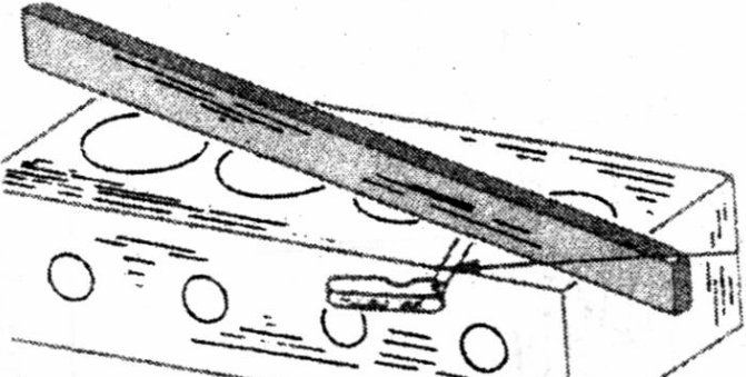
Thoroughly clean the cylinder head surface and measure the surface for distortion. To do this, place a fine-edge steel ruler across the cylinder head face as shown in Fig. 1.56 and measure the gap between ruler and head with feeler gauges. If a feeler gauge of more than specified in Section 1.4.0.0. can be inserted, replace the cylinder head. The head can be re-ground as long as the min. height is retained (92.10 mm).
Camshaft:
All engines use the same camshaft. The camshaft is secured to the cylinder block by means of a keeper plate, inserted into a groove in the shaft and secured by two screws.
To remove the camshaft, remove the Woodruff key with a side cutter and un-
Parts & tools for this job For 1987 Peugeot J5
- PARTEngine gasket setSearch: Peugeot J5 1987 engine gasket set
- TOOLTorque wrenchSearch: 3/8 inch torque wrench
- TOOLFeeler gauge setSearch: feeler gauge set
Links open Amazon search results in a new tab. As an Amazon Associate I earn from qualifying purchases.