
Rear console (page 2 of 2)
- Make
- Rover
- Model
- 400 Body Repair Manual
- Year
- 1995–2000
- Section
- Interior trim components
BodyRear console · page 2 of 2
Do not carry out further dismantling if component is removed for access only.
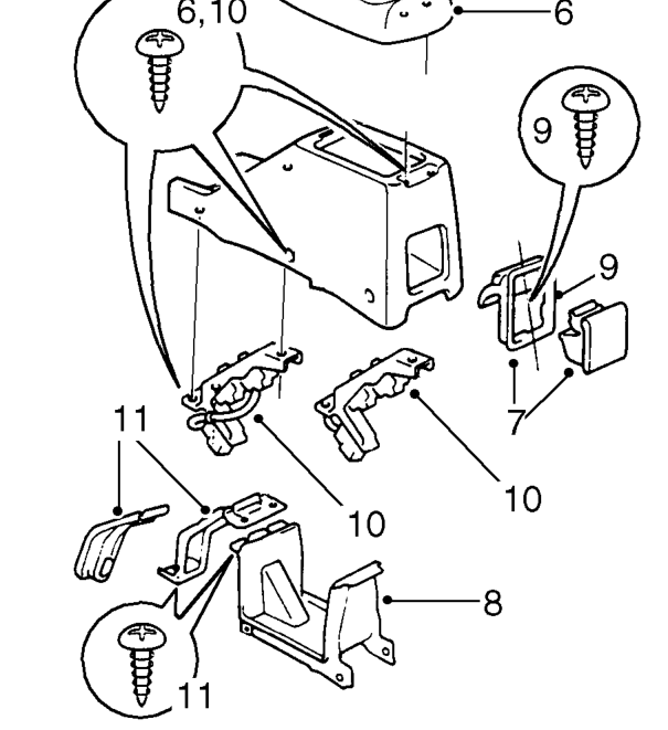
- Open console lid, remove 2 screws and remove lid.
- Remove ash tray.
- Remove 4 screws and remove oddments tray.
- Remove screw and remove ash tray flame shield.
- Remove 6 screws and remove both window lift switch assemblies.
- Remove remaining screw and remove hand brake lever grommet and its retaining plate.
- Remove nut and retaining clip from ash tray aperture.
Refit
- Fit retaining clip and nut to ash tray aperture.
- Fit hand brake lever grommet and its retaining plate. Fit lower screw to secure.
- Fit both switch assemblies and secure with screws.
NOTE: The switch assembly with the brown multiplug connection is fitted to the RH side.
- Fit ash tray flame shield and secure with screw.
- Fit oddments tray and secure with screws.
- Fit ash tray.
- Fit console lid and secure with screws.
- Fit rear console and connect window lift switch multiplugs.
- Align console and secure with screws and bolts.
- Fit bolt cover.
- Reposition front seats.
Parts & tools for this job For 1995 Rover 400
- TOOLTrim removal tool kitSearch: trim removal tool kit
- PARTTouch-up paintSearch: Rover touch up paint
- PARTPanel clip assortmentSearch: Rover panel clips assortment
Links open Amazon search results in a new tab. As an Amazon Associate I earn from qualifying purchases.