
Airbag harness ’k’ ’l’ and ’t’ series
- Make
- Rover
- Model
- 400 Workshop Manual
- Year
- 1995–2000
- Section
- Repairs › Airbag harness ’k’ ’l’ and ’t’ series
Restraint systemsAirbag harness ’k’ ’l’ and ’t’ series · page 1 of 3
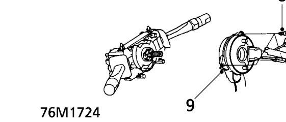
- Remove 3 screws securing rotary coupler to column switch assembly.
- Remove rotary coupler.
Refit
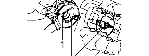
- Align the slots in the rotary coupler with the projections on the turn signal cancelling sleeve and secure to column switch assembly with screws.
- Remove retaining tape from rotary coupler.
- Pass rotary coupler flat harness through the lower cover bracket and fit retaining strap.
- Connect rotary coupler harness to SRS harness multiplug.
- Fit column lower and upper covers, secure with screws.
- Fit driver’s side closing panel, secure with screws and fit pocket.
- Fit steering wheel. See STEERING, Repairs.
- Fit drivers airbag module. See this section.
AIRBAG HARNESS ’K’ ’L’ AND ’T’ SERIES
Service repair no - 76.73.73
CAUTION: See safety precautions before commencement of repair.
Remove
- Remove key from starter switch, disconnect both battery leads, earth lead first, and wait 10 minutes for the SRS back-up power circuit to discharge before commencing work.
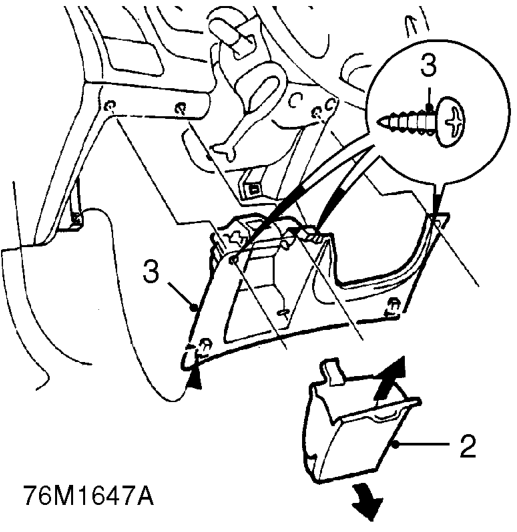
- Remove pocket from drivers side closing panel.
- Remove 3 screws and remove closing panel.
- Remove 3 screws then carefully separate and remove upper and lower sections of column nacelle.
- Remove glove box. See BODY, Interior trim components.
- Remove front console. See BODY, Interior trim components.
Parts & tools for this job For 1995 Rover 400
- TOOLOBD2 scanner with SRSSearch: OBD2 scanner ABS SRS
- TOOLTrim removal tool kitSearch: trim removal tool kit
Links open Amazon search results in a new tab. As an Amazon Associate I earn from qualifying purchases.