Workshop Manuals Factory service & repair Rover
01 Information02 General data03 Engine04 Engine management system – PGM-Fi05 Cooling system, manifold and exhaust06 Clutch07 Manual gearbox08 Automatic gearbox09 Drive shafts10 Differential – manual gearbox11 Differential – automatic gearbox12 Steering13 Suspension14 Brakes and ABS15 Brakes – ABS BY416 Body17 Heating and ventilation18 Electrical19 Supplementary restraint system (SRS)
Rover Rover 600 Repair Manual - Volumes 1 and 2 - 2nd Edition03 · Engine
03 · Engine

Remove (page 2 of 7)

Make
Rover
Model
600 Rover 600 Repair Manual - Volumes 1 and 2 - 2nd Edition
Section
Engine remove: repairs
EngineRemove · page 2 of 7
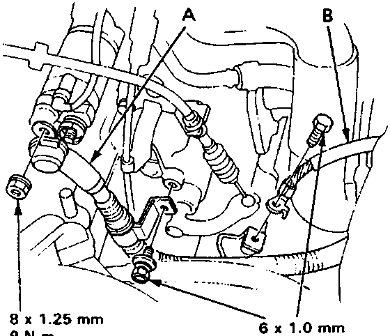
Diagram showing starter cable and gearbox earth cable with dimensions 8 x 1.25 mm 9 N m and 6 x 1.0 mm 10 N m
A Starter cable B Earth cable 10. Remove the starter cable and gearbox earth cable. 11. Relieve fuel pressure by slowly loosening the service bolt on the fuel rail about one turn, see ENGINE MANAGEMENT SYSTEM – PGM-Fi.

WARNING: Do not smoke while working on the fuel system. Keep away from work area. Drain fuel only into an approved container.

CAUTION:

  • Before disconnecting any fuel line, relieve the fuel pressure as described above.
  • Place a shop towel over the fuel rail to prevent pressurised fuel from spraying over the engine.
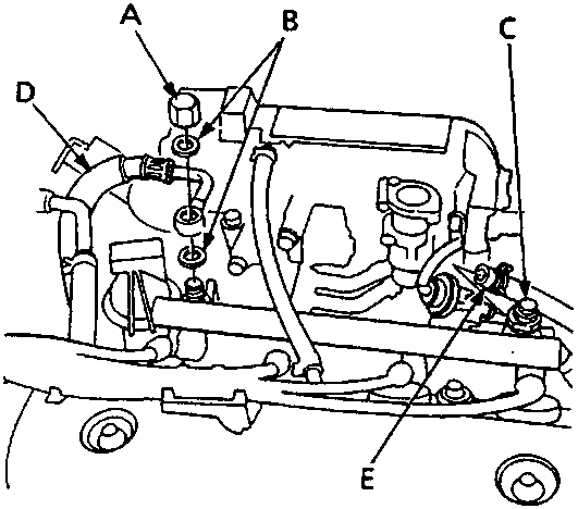
Diagram showing banjo nut, washers, service bolt, fuel return hose and fuel feed hose
A Banjo nut B Washers (replace) C Service bolt D Fuel return hose E Fuel feed hose 12. Remove the fuel feed hose and fuel return hose.
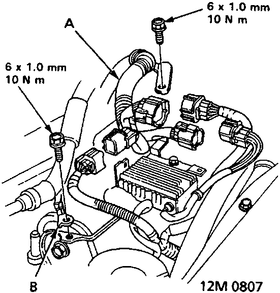
Diagram showing left side engine harness and earth cable with dimensions 6 x 1.0 mm 10 N m
A Left side engine harness B Earth cable 13. Remove the left side engine harness and earth cable.

Parts & tools for this job For Rover 600

Links open Amazon search results in a new tab. As an Amazon Associate I earn from qualifying purchases.