Workshop Manuals Factory service & repair Rover
01 Information02 General data03 Engine04 Engine management system – PGM-Fi05 Cooling system, manifold and exhaust06 Clutch07 Manual gearbox08 Automatic gearbox09 Drive shafts10 Differential – manual gearbox11 Differential – automatic gearbox12 Steering13 Suspension14 Brakes and ABS15 Brakes – ABS BY416 Body17 Heating and ventilation18 Electrical19 Supplementary restraint system (SRS)
Rover Rover 600 Repair Manual - Volumes 1 and 2 - 2nd Edition03 · Engine
03 · Engine

Remove (page 5 of 7)

Make
Rover
Model
600 Rover 600 Repair Manual - Volumes 1 and 2 - 2nd Edition
Section
Engine remove: repairs
EngineRemove · page 5 of 7
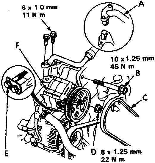
Diagram of power steering pump assembly showing mounting bolts, adjusting bolt, and P/S pipe with torque specifications 6x1.0mm 11Nm, 10x1.25mm 45Nm, and 8x1.25mm 22Nm
A P/S pipe B Mounting bolt C P/S pump belt D Mounting nut E Adjusting bolt F P/S pump 21. Remove the power steering (P/S) pipe and mounting bolt/nut. Loosen the adjusting bolt, then remove the P/S pump belt and pump. Note: • Plug the pipe and the pump port. • Do not disconnect the hose.
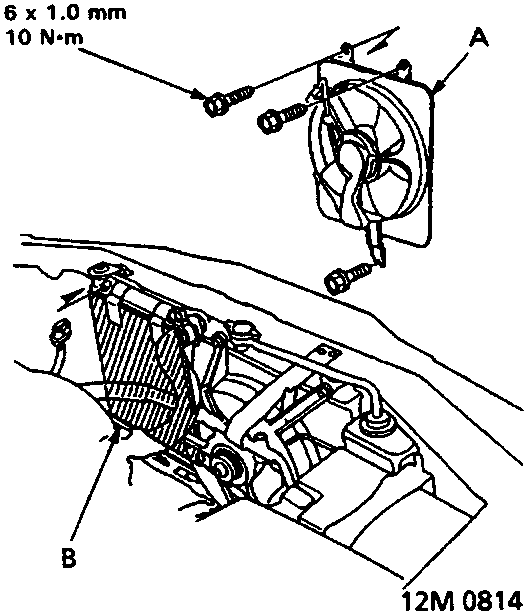
Diagram showing condenser fan shroud being removed from radiator area with a protector plate installed below
A Condenser fan shroud B Protector plate 22. Remove the condenser fan shroud then install a protector plate to the radiator.
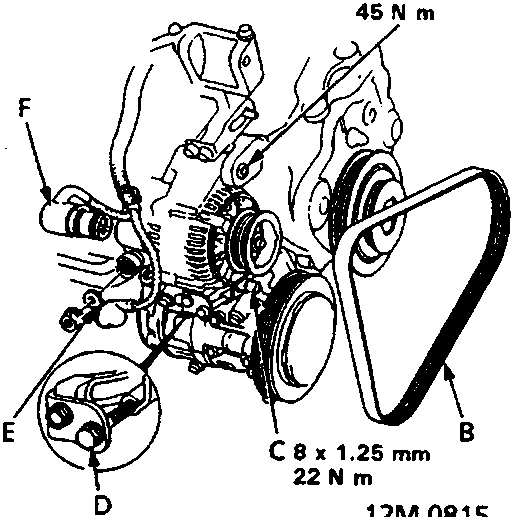
Diagram of alternator assembly showing mounting bolt, alternator belt, adjusting bolt, terminal, and connector with torque specifications 10x1.25mm 45Nm and 8x1.25mm 22Nm
A Mounting bolt B Alternator belt C Mounting nut D Adjusting bolt E Alternator terminal F Alternator connector

Parts & tools for this job For Rover 600

Links open Amazon search results in a new tab. As an Amazon Associate I earn from qualifying purchases.