
Remove (page 7 of 7)
- Make
- Rover
- Model
- 600 Rover 600 Repair Manual - Volumes 1 and 2 - 2nd Edition
- Section
- Engine remove: repairs
EngineRemove · page 7 of 7
- Remove the shift cable and select cable (M/T).
Note:
- Take care not to bend the cable when removing it. Always replace any kinked cable with a new one.
- Adjust the shift cable when installing, see MANUAL GEARBOX.
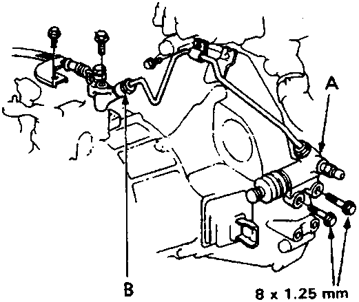
- A Slave cylinder
- B Clutch house joint
- Remove the clutch slave cylinder and the pipe/hose assembly (M/T).
Note:
- Do not operate the clutch pedal once the slave cylinder has been removed.
- Take care, not to bend the pipe.
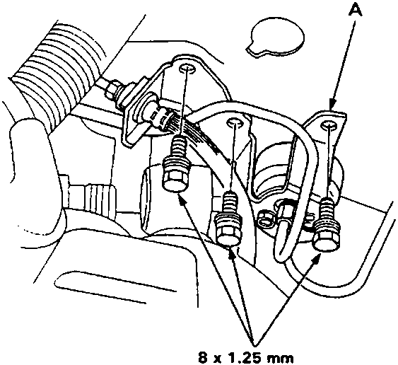
- A Clutch damper assembly
- Remove the clutch damper assembly (M/T).
Note: Take care, not to bend the pipe.
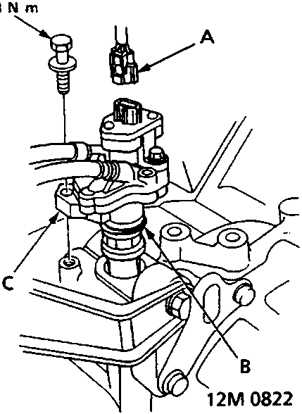
- A Connector
- B 'O' ring
- C Vehicle/Power steering speed sensor
- Remove the vehicle speed sensor /power steering speed sensor assembly.
Note: Do not disconnect the hoses.
- Raise the hoist to full height.
Parts & tools for this job For Rover 600
- PARTEngine gasket setSearch: Rover 600 engine gasket set
- TOOLTorque wrenchSearch: 3/8 inch torque wrench
- TOOLFeeler gauge setSearch: feeler gauge set
Links open Amazon search results in a new tab. As an Amazon Associate I earn from qualifying purchases.