
Remove (page 3 of 7)
- Make
- Rover
- Model
- 600 Rover 600 Repair Manual - Volumes 1 and 2 - 2nd Edition
- Section
- Engine remove: repairs
EngineRemove · page 3 of 7
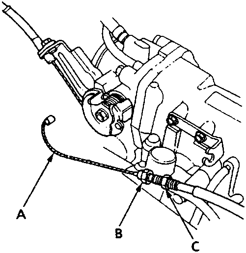
A Cable end
B Locknut
C Adjusting nut
- Remove the throttle cable by loosening the locknut, then slip the cable end out of the throttle linkage.
Note:
- Do not loosen the adjusting nut.
- Take care not to bend the cable when removing it. Always replace any kinked cable with a new one.
- Adjust the throttle cable when installing, see ENGINE MANAGEMENT SYSTEM – PGM – Fi.
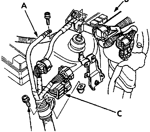
A Power cable
B Underbonnet fuse/relay box
C Engine harness
- Remove the engine harness connectors, terminal and clamps on the right side of the engine compartment.
- Remove the power cable from the underbonnet fuse/relay box.
Parts & tools for this job For Rover 600
- PARTEngine gasket setSearch: Rover 600 engine gasket set
- TOOLTorque wrenchSearch: 3/8 inch torque wrench
- TOOLFeeler gauge setSearch: feeler gauge set
Links open Amazon search results in a new tab. As an Amazon Associate I earn from qualifying purchases.