
32. Remove the exhaust pipe.
- Make
- Rover
- Model
- 600 Rover 600 Repair Manual - Volumes 1 and 2 - 2nd Edition
- Section
- Engine remove: repairs › 32. Remove the exhaust pipe.
Engine32. Remove the exhaust pipe. · page 1 of 9
● Adjust the shift cable when installing, see AUTOMATIC GEARBOX.
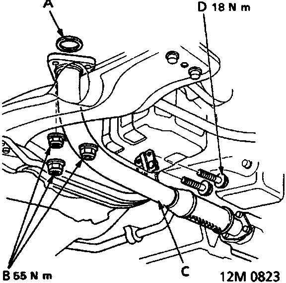
- A Gasket (replace)
- B Self locking nut (replace)
- C Exhaust pipe
- D Self locking bolt (replace)
32. Remove the exhaust pipe.
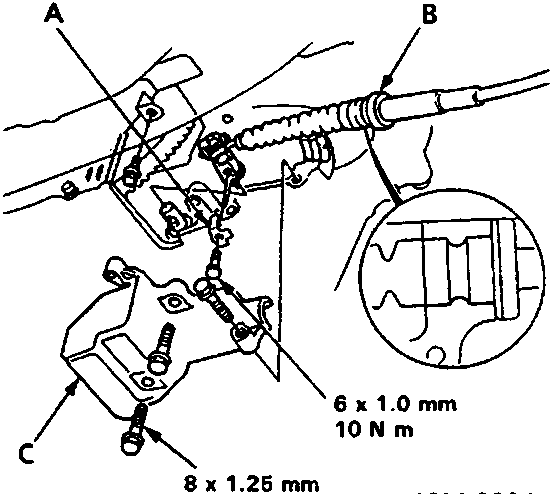
- A Lock washer (replace)
- B Shift cable
- C Cover
33. Remove the A/T shift cable (A/T).
Note:
● Take care not to bend the cable when removing it. Always replace any kinked cable with a new one.
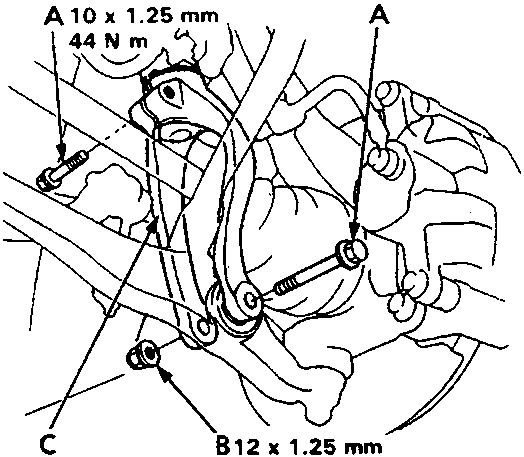
- A Self - locking bolt
- B Self - locking nut
- C Damper fork
34. Remove the damper fork.
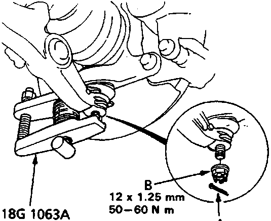
- A Cotter pin (replace)
- B Castle nut
35. Disconnect the suspension lower arm ball joint with the special tool, see SUSPENSION.
CAUTION: Insert the jaws carefully, making sure you do not damage the ball joint boot.
Parts & tools for this job For Rover 600
- PARTExhaust gasketSearch: Rover 600 exhaust gasket
- TOOLPenetrating oilSearch: penetrating oil
- TOOLOBD2 scannerSearch: OBD2 scanner
Links open Amazon search results in a new tab. As an Amazon Associate I earn from qualifying purchases.