
32. Remove the exhaust pipe. (page 9 of 9)
- Make
- Rover
- Model
- 600 Rover 600 Repair Manual - Volumes 1 and 2 - 2nd Edition
- Section
- Engine remove: repairs
Engine32. Remove the exhaust pipe. · page 9 of 9
32. Remove the exhaust pipe. (page 9 of 9) – diagram from the Engine chapter of the Rover Rover 600 Repair Manual - Volumes 1 and 2 - 2nd Edition factory manual.
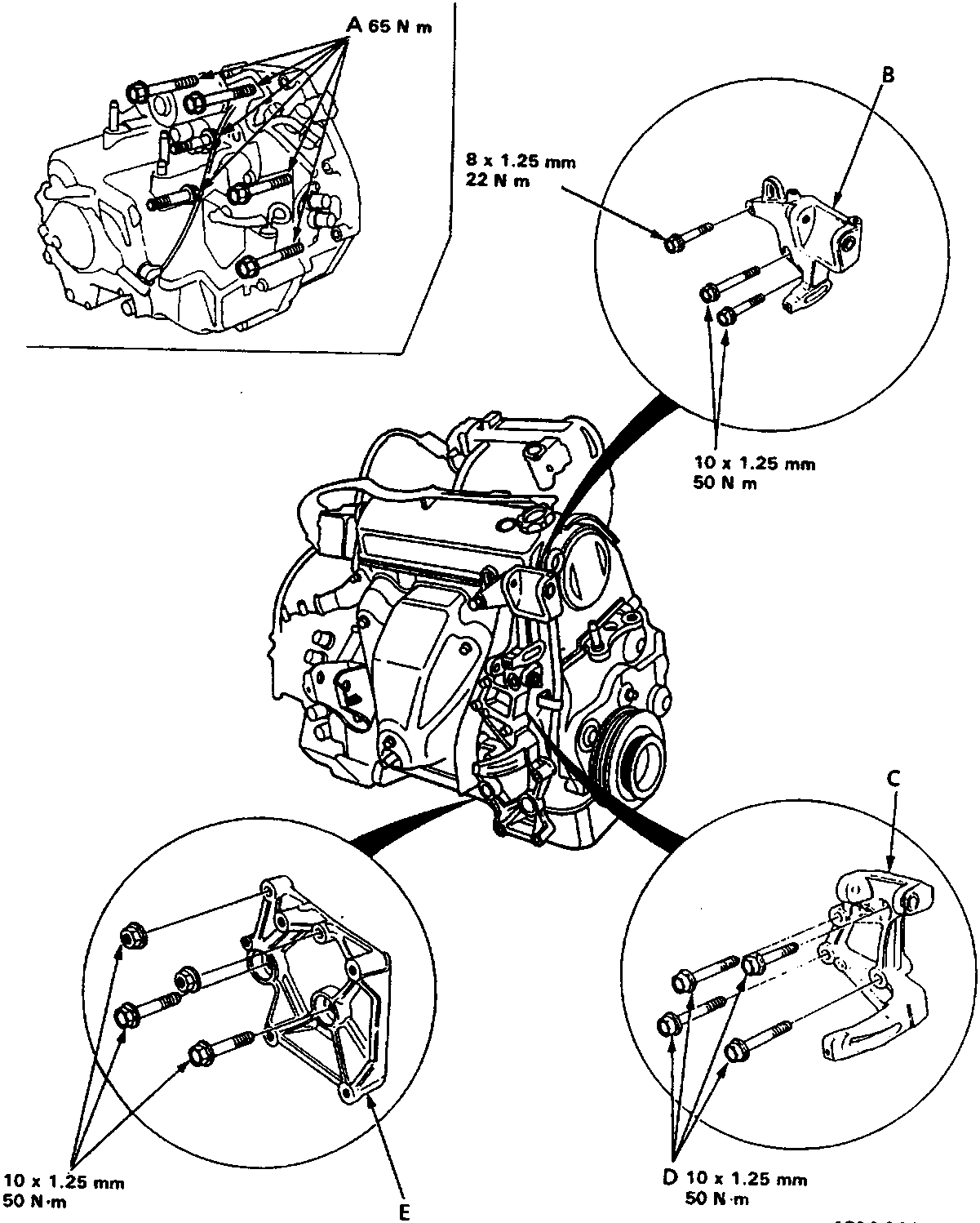
- A Gearbox mount bolts
- B P/S bracket
- C Alternator bracket
- D (Apply liquid gasket)
- E A/C bracket
Parts & tools for this job For Rover 600
- PARTExhaust gasketSearch: Rover 600 exhaust gasket
- TOOLPenetrating oilSearch: penetrating oil
- TOOLOBD2 scannerSearch: OBD2 scanner
Links open Amazon search results in a new tab. As an Amazon Associate I earn from qualifying purchases.