
Flow Chart – Blower Motor (page 4 of 5)
- Make
- Rover
- Model
- 600 Rover 600 Repair Manual - Volumes 1 and 2 - 2nd Edition
- Section
- Information
Heating and ventilationFlow Chart – Blower Motor · page 4 of 5
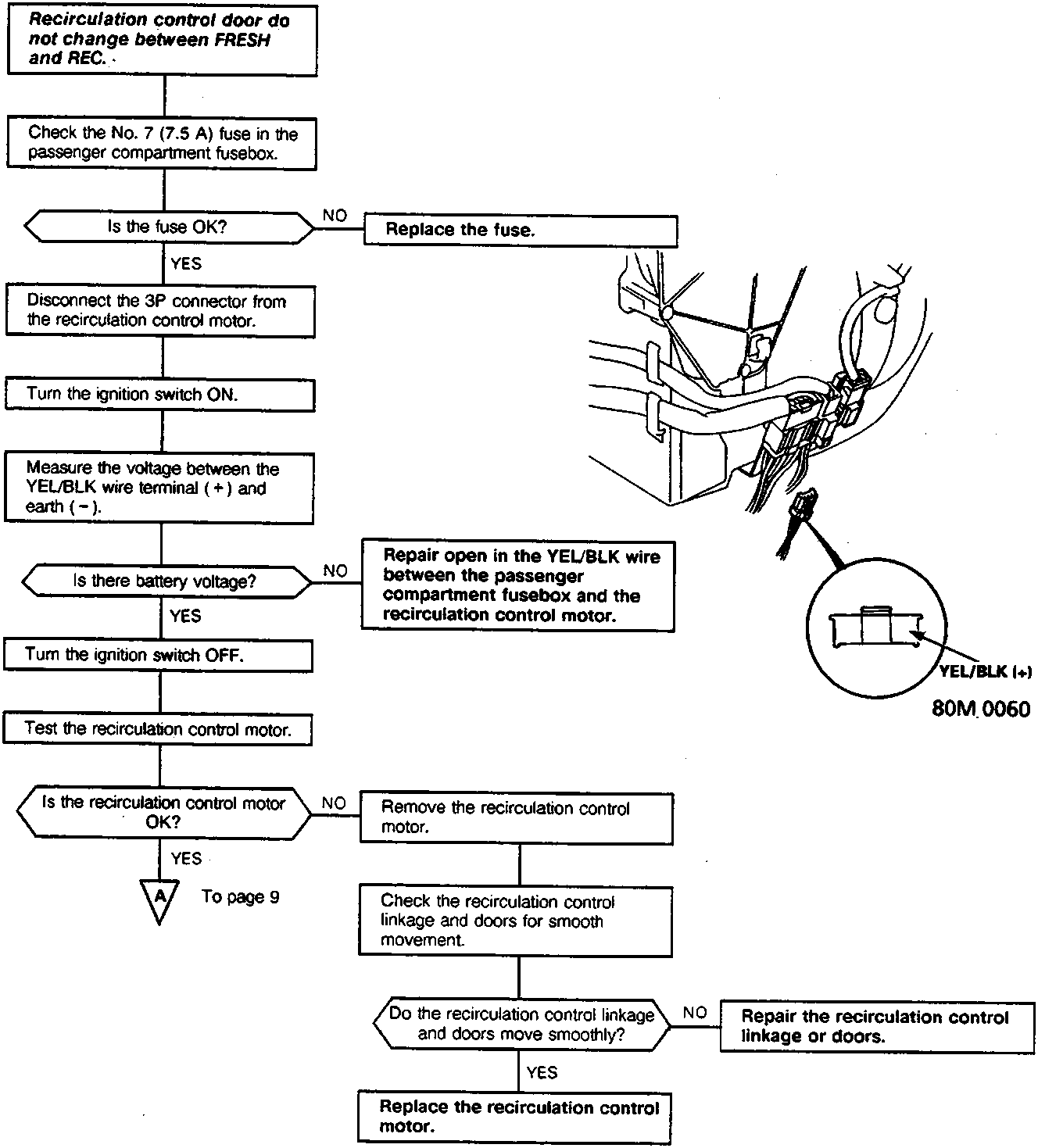
Recirculation control door do not change between FRESH and REC.
- Check the No. 7 (7.5 A) fuse in the passenger compartment fusebox.
Is the fuse OK?
- NO: Replace the fuse.
- YES: Disconnect the 3P connector from the recirculation control motor.
- Turn the ignition switch ON.
- Measure the voltage between the YEL/BLK wire terminal (+) and earth (-).
Is there battery voltage?
- NO: Repair open in the YEL/BLK wire between the passenger compartment fusebox and the recirculation control motor.
- YES: Turn the ignition switch OFF.
- Test the recirculation control motor.
Is the recirculation control motor OK?
- NO: Remove the recirculation control motor.
Check the recirculation control linkage and doors for smooth movement.
Do the recirculation control linkage and doors move smoothly?
NO: Repair the recirculation control linkage or doors.
YES: Replace the recirculation control motor. - YES: To page 9
Parts & tools for this job For Rover 600
- TOOLA/C manifold gauge setSearch: AC manifold gauge set
- TOOLUV leak detection kitSearch: AC UV leak detection kit
- PARTCabin filterSearch: Rover 600 cabin filter
Links open Amazon search results in a new tab. As an Amazon Associate I earn from qualifying purchases.