
Remove
- Make
- Rover
- Model
- Coupé, Cabriolet & Tourer 200/400 Coupé, Cabriolet & Tourer Workshop Manual
- Section
- Repairs › Remove
Supplementary restraint system (SRS)Remove
Remove
- Remove key from starter switch and disconnect both battery leads, earth lead first.
- Wait 10 minutes to allow SRS back – up power circuit to discharge before commencing work.
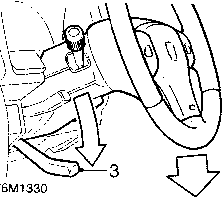
- Lower column and secure adjusting lever.
- Remove drivers airbag module, see Drivers airbag module.
- Remove steering wheel, see Steering wheel.
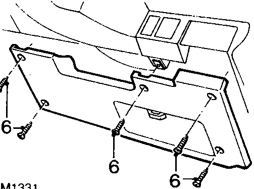
- Remove 5 screws securing fusebox cover.
- Release and remove fusebox cover from fascia.
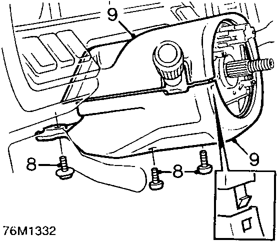
- Remove 3 screws securing lower half of nacelle to steering column.
- Release 2 clips securing front edge of nacelle then seperate 2 halves of nacelle and remove.
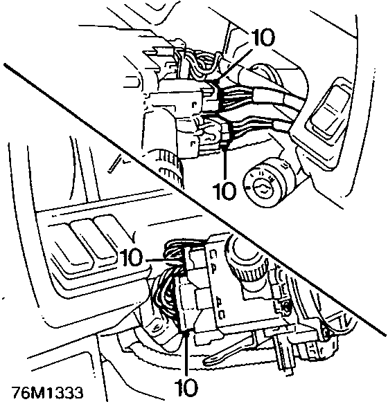
- Disconnect 4 multiplugs from column switch assembly.
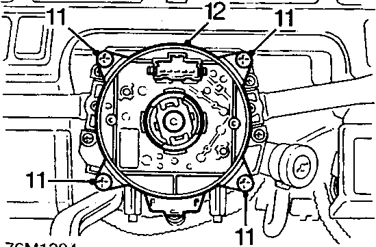
- Remove 4 screws securing slip ring to column switch assembly.
- Release slip ring from column and position aside.
Parts & tools for this job For Rover Coupé, Cabriolet & Tourer
- TOOLOBD2 scanner with SRSSearch: OBD2 scanner ABS SRS
- TOOLTrim removal tool kitSearch: trim removal tool kit
Links open Amazon search results in a new tab. As an Amazon Associate I earn from qualifying purchases.