Power transmissionDismantling and assembling gearbox
| –
| Secure gearbox to engine and gearbox support -VW 540- → Chapter. |
|
|
|
| –
| Remove slave cylinder with clutch release bearing -arrows A-. |
| Gearbox for front-wheel drive |
| –
| Remove securing bolt for right stub shaft -arrow B-. |
| Continuation for all vehicles |
| –
| Place drip tray under the engine. |
| –
| Remove bolts for securing clutch housing to gearbox housing. |
|
|

|
| –
| Lock input shaft -B-, to do this place the installing sleeve -VW 455- over the input shaft on the clutch housing. |
| –
| Secure splitter 5 ... 60 mm-A-, for example splitter with quick clamping spindle (inner diameter 5 - 60 mm) -KUKKO 17/0-, behind the input shaft splines. |
| l
| No play can be present between splitter and installing sleeve. |
|
|

|
| –
| Gearboxes for vehicles with start-stop system: remove gearbox neutral position sender -G701--arrow-. |
| –
| Place selector shaft of selector unit in neutral. |
| –
| Remove reversing light switch -F4--A-. |
| –
| Remove bolts for selector unit -B- from gearbox housing. |
| –
| Pull selector unit out of gearbox housing while turning selector unit 180°. |
| l
| Selector fingers of selector unit must be guided through selector rods. |
| –
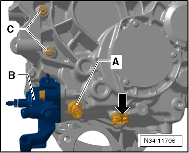
| Remove hexagon nuts -C-. |
|
|
|
| –
| If present, remove tachograph sender -G75--A--arrow-. |
|
|

|
| –
| Remove locking plate -1-. |
|
|

|
| –
| Or remove retaining clip -2-. |
|
|

|
| –
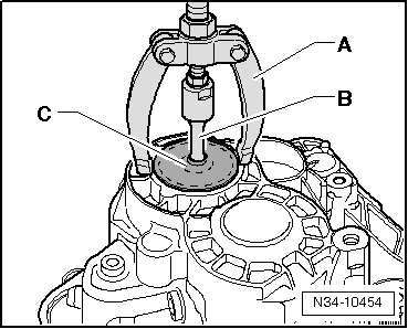
| Pierce rubber in centre of cover plate -C- with a screwdriver. |
| –
| Pull sealing cover out of gearbox housing. |
| –
| If necessary, pull cover out of gearbox housing. |
| A - | e. g. Counter support |
| B - | Internal puller, 14.5…18.5 mm, e.g. -Kukko 21/02- |
|
|
|
| Remove retaining ring -C- from deep groove ball bearing of input shaft as follows: |
| –
| Hold end of retaining ring with screwdriver -A-. |
| –
| With a second screwdriver -B-, lever other end of retaining ring out of groove in deep groove ball bearing -arrow-. |
| –
| Continue to lever out retaining ring with screwdriver -B-. |
|
|

|
| –
| Unscrew securing bolts from the left stub shaft -A-, to do this the stub shaft must be locked using the counterhold -T10371-. |
| –
| Remove bolts securing gearbox housing to clutch housing. |

Note | If bolts -B- are present, they do not need to be removed in order for gearbox housing to be removed. |
|
|

|
| –
| Screw multipurpose tool -VW 771/44- into threaded hole of gearbox housing to stop and counterlock with nut -A-. |
| –
| Heat the gearbox housing e.g. using hot air blower -VAG 1416- in area round bearing seats for grooved ball bearing/input shaft for approx. 10 minutes long to approx. 100 °C. |
| –
| Separate the gearbox housing from clutch housing using the multipurpose tool -VW 771-. At the same time separate gearbox housing on housing web -arrow- from clutch housing using assembly tool -B-. |
|
|

|
| –
| Remove splitter -A- and installing sleeve -VW 455- from input shaft -B-. |
|
|
|
| –
| Remove reverse gear selector fork -A-. |
| –
| If necessary, carefully tilt gearbox slightly to side. |
|
|

|
| –
| Lift input shaft -1- in direction of -arrow-, until the pulley counterhold -3435- can be inserted. |
| –
| Swing gearbox back to original horizontal position. |
|
|

|
| –
| Secure stub shaft -1- to differential so that differential can be raised during the following steps. |
| –
| Carefully tilt gearbox slightly to side. |
|
|

|
| –
| Press output shaft for 1st and 2nd gears -B- up to stop. |
| –
| Then swing reverse gear output shaft -A- out. |

Caution | Gearbox components might come loose inadvertently when tilted. |
| To prevent this happening, swing gearbox back to original horizontal position. |
|
| –
| Then remove output shaft for 1st and 2nd gears -B- together with selector rod -C- from clutch housing. |
|
|

|
| –
| Pull out differential -3- on stub shaft. |
Note | Always renew deep groove ball bearing on input shaft ⇒ Assembly overview - input shaft → Item. |
|
|

|
01 Transmission
The same page in:
Leon Mk2.