Rear Disc Brake Pads Replacement
Special Tools
| • |
CH-6007-B Disc
Brake Piston Installation Tool |
For equivalent regional tools, refer to
Special Tools .
Removal Procedure
| 1. |
Inspect the fluid level in the
brake master cylinder reservoir. |
| 2. |
If the brake fluid level is
midway between the maximum-full point and the minimum allowable
level, no brake fluid needs to be removed from the reservoir before
proceeding. |
| 3. |
If the brake fluid level is
higher than midway between the maximum-full point and the minimum
allowable level, remove brake fluid to the midway point before
proceeding. |

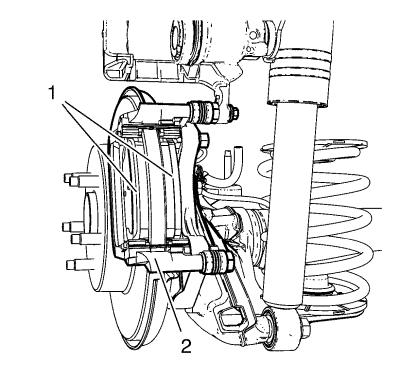
| 6. |
Remove the brake caliper
vibration dampener (2). |
|
Caution: Support the brake caliper with heavy mechanic wire, or
equivalent, whenever it is separated from its mount and the
hydraulic flexible brake hose is still connected. Failure to
support the caliper in this manner will cause the flexible brake
hose to bear the weight of the caliper, which may cause damage to
the brake hose and in turn may cause a brake fluid leak.
|
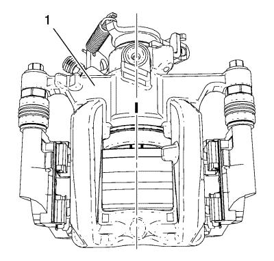
| 7. |
Without disconnecting the
hydraulic brake flexible hose, pivot the caliper (1) upward and
secure the caliper with heavy mechanics wire, or equivalent.
|
| |
Mark the brake caliper piston position to the brake caliper
(1). |
| 8. |
Remove the brake pads (1) from
the caliper mounting bracket (2). |
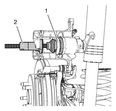
| 9. |
Turn back the disc brake
calliper piston (1) into the calliper bore using the
CH-6007-B installation tool with
CH-6007-50 adapter (2). |
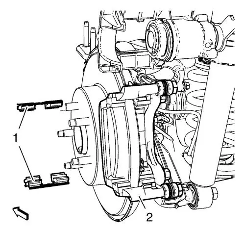
| 10. |
Remove the brake pad retainer
springs (1) from the caliper bracket (2). |
| 11. |
Thoroughly clean the brake pad
hardware mating surfaces of the caliper bracket, of any debris and
corrosion. |
| 12. |
Inspect the brake caliper
guide pins for freedom of movement, and inspect the condition of
the guide pin boots. Move the guide pins inboard and outboard
within the bracket bores, without disengaging the slides from the
boots, and observe for the following: |
| |
• |
Restricted caliper guide pin
movement |
| |
• |
Looseness in the brake caliper
mounting bracket |
| |
• |
Seized or binding caliper
guide pins |
| 13. |
If any of the conditions
listed are found, the brake caliper guide pins and/or boots require
replacement. |
Installation Procedure
| 1. |
Ensure the brake pad hardware
mating surfaces are clean. |
| 2. |
Install the brake pad
retainers springs (1) to the brake caliper bracket (2) and apply a
thin coat of high temperature silicone lube to the brake pad
retainers. |
|
Note: The wear sensor
equipped disc brake pad must be mounted inboard of the rotor with
the leading edge of the sensor facing the brake rotor during
forward wheel rotation, or at the top of the pad when installed in
vehicle position.
|
| 3. |
Install the brake pads (1) to
the caliper bracket (2). |
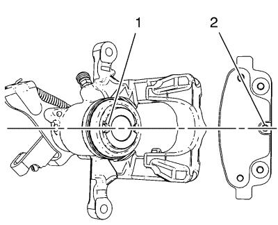
| 4. |
Check the correct position of
disc brake caliper piston (1). |
| |
Cavities for brake pad anti rotation pin (2) must be aligned as
shown in graphic, in order to ensure an appropriate mounting onto
the inner brake pad. |
| 5. |
Remove the support, and rotate
the brake caliper (1) into position over the disc brake pads and to
the caliper mounting bracket. |
| 6. |
Install the lower brake
caliper mass dampener (2) and tighten to 28 N·m (21
lb ft) . |
| 7. |
Checking position of piston
cavity after assembling caliper (1) |
| 10. |
With the engine OFF, gradually
apply the brake pedal approximately 2/3 of its travel
distance. |
| 11. |
Slowly release the brake
pedal. |
| 12. |
Wait 15 seconds, then
gradually apply the brake pedal approximately 2/3 of its travel
distance again until a firm brake pedal apply is obtained. This
will properly seat the brake caliper pistons and brake pads.
|
|
