
Main and rod bearing halves
- Make
- Alfa Romeo
- Model
- 145/146 Engines, 146 Bodywork and Engine Overhaul Manual
- Year
- 1994–2001
- Section
- Overhauling › Main and rod bearing halves
MAIN AND ROD BEARING HALVES
These are of the three-metal, thin shell type, divided into three dimensional classes, for the main bearing halves and two for the connecting rod bearing halves.
FLYWHEEL
This is in cast iron with a hardened ring gear and suitably balanced.
PISTONS - CONNECTING RODS
The pistons are in aluminium-silicon alloy with self-heating inserts and are divided into three dimensional classes. To ensure correct assembly an arrow is stamped on the piston crown to indicate the direction of rotation of the engine.
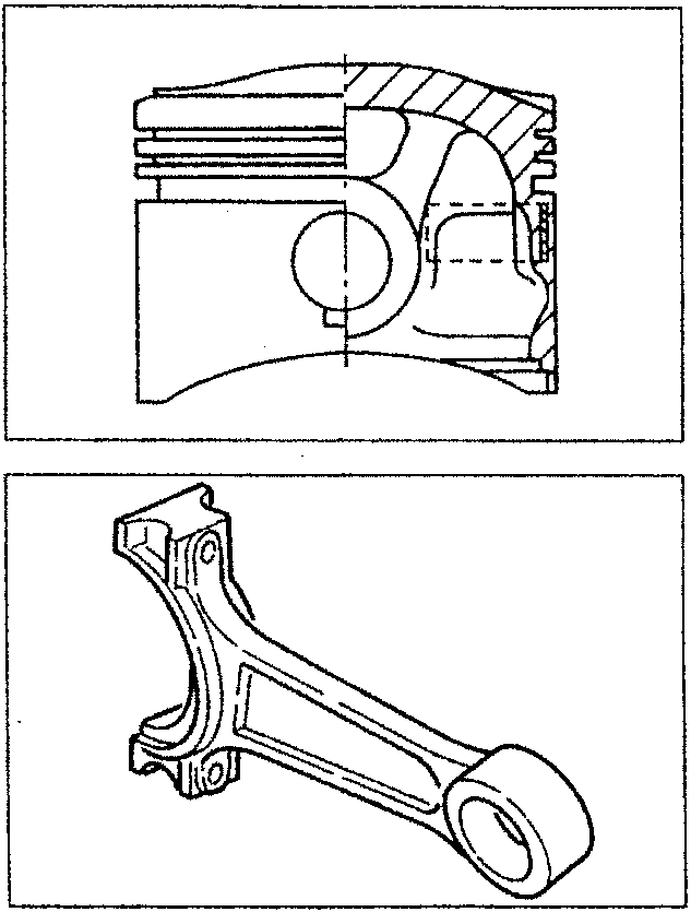
The connecting rods are in hardened and tempered alloy steel with a bushing in copper alloy force-fitted for coupling with the piston gudgeon pin.
As the gudgeon pins are floating on the piston hubs and on the connecting rod small end, their side movement is stopped by two expansion circlips housed in the special hollows machined on the actual hubs.
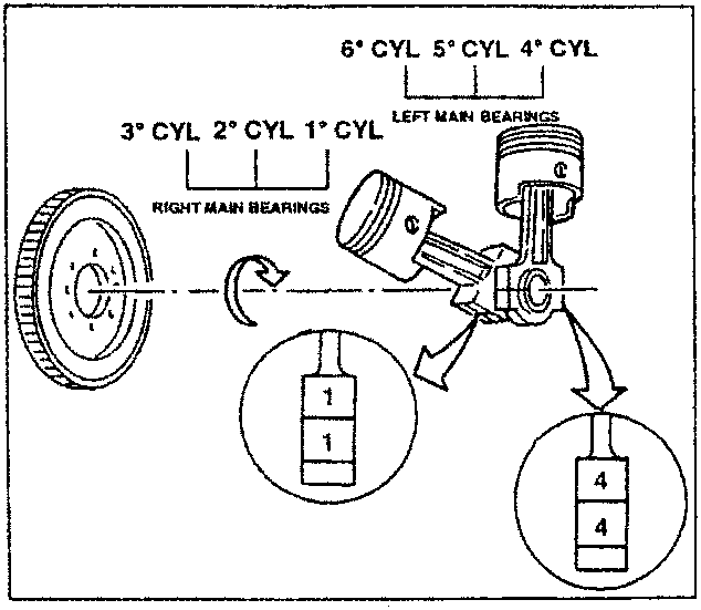
Each connecting rod is stamped with the number of the cylinder to which it refers; this number is towards the righthand side of the connecting rods of the right main bearings and on the lefthand side of the connecting rods of the left main bearings. Also the connecting rod caps have the number of the cylinder to which they refer on one side. When refitting this number should be on the same side as the one stamped on the connecting rod big end.
Parts & tools for this job For 1994 Alfa Romeo 145/146
- PARTEngine gasket setSearch: Alfa Romeo 145/146 1994 engine gasket set
- TOOLTorque wrenchSearch: 3/8 inch torque wrench
- TOOLFeeler gauge setSearch: feeler gauge set
Links open Amazon search results in a new tab. As an Amazon Associate I earn from qualifying purchases.