
Alternator - r+r
- Make
- Alfa Romeo
- Model
- 147 Factory Service Manual
- Year
- 2000–2004
- Section
- Current generator › Alternator - r+r
Alternator - r+r
Removing
Position the vehicle on the ramp.
Ensure that the ignition key is in the OFF position, then disconnect the negative battery terminal (-).
| Name | Connector | |
|---|---|---|
| Battery | A1B |
Proceed with the removal - 4450B10 Front WHEEL (one) - R.R. (Right side).
Proceed with the removal - 7055B64 Engine compartment DUST shield in front wheel arch (one), left or right - R.R. (Right side).
Proceed with removal - 1092G10 single engine belt r r.
Proceed with removal - 1072C44 exhaust manifold heat shield on bulkhead - r+r.
Proceed with removal - 1080B62 catalytic converter - r + r.
Proceed with removal - 1080B40 catalytic pre-converter - r r.
Proceed with removal - 4410A80 damper lower fork - r r.
Proceed with removal - 2710A31 intermediate drive shaft - r r.
1. Disconnect the electrical connection from the engine oil pressure warning light switch.
| Name | Connector | |
|---|---|---|
| 1 | Engine oil pressure sensor | K30 |
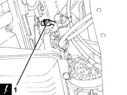
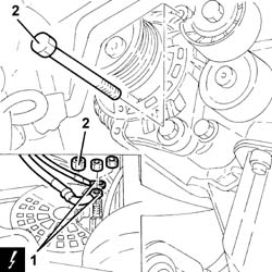
1. Disconnect the electrical connections from the alternator.
| Name | Connector | |
|---|---|---|
| 1 | Alternator | A10 |
2. Undo the upper alternator fixing bolt.
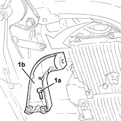
1. Undo the bolts (1a) and remove the alternator rear bracket (1b).
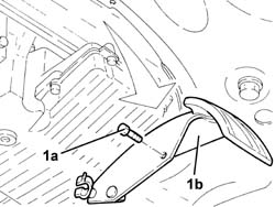
1. Undo the bolt (1a) and remove the power assisted steering pump protection (1b).
Proceed with removal - 1008A44 rear rigid mount - r r.
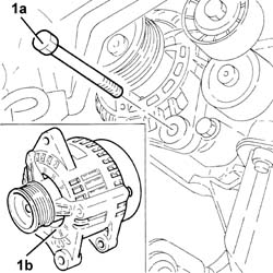
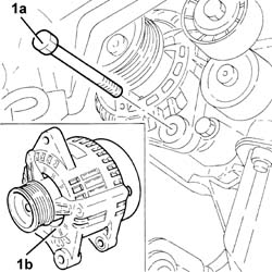
1. Undo the lower bolt (1a) and remove the alternator (1b).
Refitting
Refit the alternator in its seating and secure it temporarily with the bottom bolt.
Refit the alternator rear bracket in its seating and fix it using the bolts.
Tighten the two bolts fixing the alternator to the recommended torque.
| Fastening | Component | Ø | Value (daNm) | |
|---|---|---|---|---|
| Bolt | ALTERNATOR ASSEMBLY | M10 | 5.0 |
| Fastening | Component | Ø | Value (daNm) | |
|---|---|---|---|---|
| Bolt | ALTERNATOR ASSEMBLY | M10 | 5.0 |
Connect the electrical connections to the alternator.
Place the power assisted steering pump pulley protection back in its housing and secure it using the bolt.
Proceed with refitting - 1008A44 rear rigid mount - r r.
Place the modular intake manifold mounting bracket back in its housing and secure it using the bolts.
Secure the electrical wiring to the bands on the modular intake manifold mounting bracket.
Connect the electrical connection to the engine oil pressure warning light switch.
Proceed with refitting - 2710A31 intermediate drive shaft - r r.
Proceed with refitting - 4410A80 damper lower fork - r r.
Proceed with refitting - 1080B62 catalytic converter - r + r.
Proceed with refitting - 1080B40 catalytic pre-converter - r r.
Proceed with refitting - 1072C44 exhaust manifold heat shield on bulkhead - r+r.
Proceed with refitting - 1092G10 single engine belt r r.
Proceed with the refitting - 7055B64 Engine compartment DUST shield in front wheel arch (one), left or right - R.R. (Right side).
Proceed with the refitting - 4450B10 Front WHEEL (one) - R.R. (Right side).
Connect the battery terminal (-).
Remove the car from the ramps.
Removing
Position the vehicle on the ramp.
Ensure that the ignition key is in the OFF position, then disconnect the negative battery terminal (-).
| Name | Connector | |
|---|---|---|
| Battery | A1B |
Proceed with the removal - 4450B10 Front WHEEL (one) - R.R. (Right side).
Proceed with the removal - 7055B64 Engine compartment DUST shield in front wheel arch (one), left or right - R.R. (Right side).
Proceed with removal - 7055B54 under-engine guard - r r.
Proceed with removal - 1092G10 single engine belt r r.
Proceed with removal - 1080B40 catalytic pre-converter - r r.
Proceed with removal - 4410A80 damper lower fork - r r.
Proceed with removal - 2710A31 intermediate drive shaft - r r.
1. Disconnect the electrical connection from the engine oil pressure warning light switch.
| Name | Connector | |
|---|---|---|
| 1 | Engine oil pressure sensor | K30 |
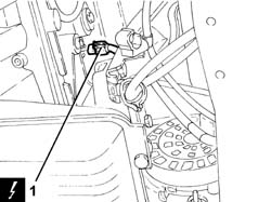
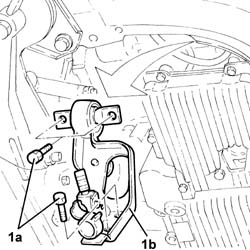
1. Undo the bolts (1a) and remove the modular intake manifold mounting bracket (1b) after having released it from the electrical wiring.
1. Disconnect the electrical connections from the alternator.
| Name | Connector | |
|---|---|---|
| 1 | Alternator | A10 |
2. Undo the upper alternator fixing bolt.
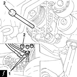
1. Undo the bolts (1a) and remove the alternator rear bracket (1b).
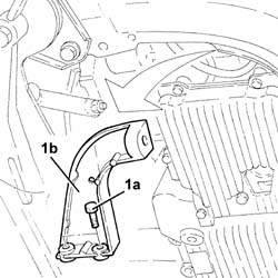
1. Undo the bolt (1a) and remove the power assisted steering pump protection (1b).
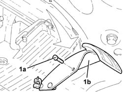
Proceed with removal - 1008A44 rear rigid mount - r r.
1. Undo the lower bolt (1a) and remove the alternator (1b).
Refitting
Refit the alternator in its seating and secure it temporarily with the bottom bolt.
Refit the alternator rear bracket in its seating and fix it using the bolts.
Tighten the two bolts fixing the alternator to the recommended torque.
| Fastening | Component | Ø | Value (daNm) | |
|---|---|---|---|---|
| Bolt | ALTERNATOR ASSEMBLY | M10 | 5.0 |
| Fastening | Component | Ø | Value (daNm) | |
|---|---|---|---|---|
| Bolt | ALTERNATOR ASSEMBLY | M10 | 5.0 |
Connect the electrical connections to the alternator.
Place the power assisted steering pump pulley protection back in its housing and secure it using the bolt.
Proceed with refitting - 1008A44 rear rigid mount - r r.
Place the modular intake manifold mounting bracket back in its housing and secure it using the bolts.
Secure the electrical wiring to the bands on the modular intake manifold mounting bracket.
Connect the electrical connection to the engine oil pressure warning light switch.
Proceed with refitting - 2710A31 intermediate drive shaft - r r.
Proceed with refitting - 4410A80 damper lower fork - r r.
Proceed with refitting - 1080B40 catalytic pre-converter - r r.
Proceed with refitting - 1092G10 single engine belt r r.
Proceed with refitting - 7055B54 under-engine guard - r r.
Proceed with the refitting - 7055B64 Engine compartment DUST shield in front wheel arch (one), left or right - R.R. (Right side).
Proceed with the refitting - 4450B10 Front WHEEL (one) - R.R. (Right side).
Connect the negative (-) battery terminal.
Remove the car from the ramps.
Removing
Position the vehicle on the ramp.
Ensure that the ignition key is in the OFF position, then disconnect the negative battery terminal (-).
| Name | Connector | |
|---|---|---|
| Battery | A1B |
Proceed with removal - 1016A10 sound-proofing cover - r + r.
Proceed with removal - 4450B04 right front wheel r r.
Proceed with removal - 7055B91 Right front WHEEL ARCH LINER - R.R..
Proceed with removal - 7055B54 under-engine guard - r r.
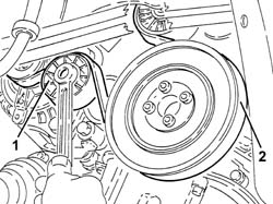
1. Adjust the moving tensioner to loosen the engine components single drive belt tension.
2. Remove the engine components single drive belt.
1. Undo the lower bolt fixing the guide pipe for the engine oil dipstick.
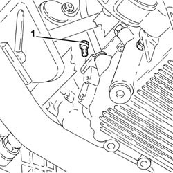
1. Undo the bolts (1a) and remove the power unit reaction rod (1b).
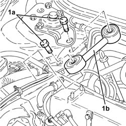
1. Disconnect the electrical connection shown from the diesel electronic injection system control unit.
| Name | Connector | |
|---|---|---|
| 1 | Engine management ECU | M10B |
2. Disconnect the front engine coupling.
| Name | Connector | |
|---|---|---|
| 2 | Front / engine coupling | D4 |
3. Disconnect the electrical connection (3a) for the air conditioning compressor and release the electrical wiring from the band (3b).
| Name | Connector | |
|---|---|---|
| 3a | Air conditioning compressor engagement electro-magnet | L20 |
4. Release the electrical wiring (4a) from the securing bands (4b), then move it.
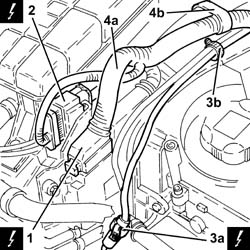
1. Release the cam angle sensor from the fastening and disconnect the electrical connection.
| Name | Connector | |
|---|---|---|
| 1 | Timing sensor. | K47 |
2. Release and rmove the engine oil dipstick.
3. Tighten the upper bolt fixing the engine oil dipstick guide pipe.
4. Release the electrical wiring from the securing band.
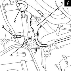
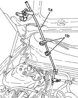
1. Remove the guide pipe for the engine oil dipstick (1a) after having release the electrical wiring from the bands (1b).
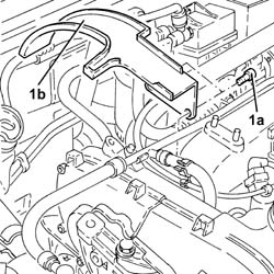
1. Undo the bolts (1a) and remove the power assisted steering pulley protection (1b).
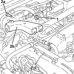
1. Undo the upper alternator fixing bolt.
2. Undo the bolts (2a) and remove the rear alternator bracket (2b).
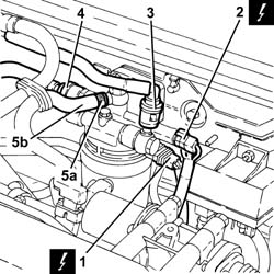
1. Disconnect the electrical connection from the fuel pre-heating device.
| Name | Connector | |
|---|---|---|
| 1 | Diesel preheating resistor | O20 |
2. Disconnect the electrical connection from the fuel temperature sensor.
| Name | Connector | |
|---|---|---|
| 2 | Fuel temperature sensor | K81 |
3. Disconnect the quick-release connector for the fuel inlet pipe, fuel filter side.
4. Disconnect the quick-release connector for the fuel supply pipe to the pressure pump, fuel filter side.
5. Loosen the band (5a) and disconnect the fuel delivery pipe to the fuel return manifold (5b), fuel filter side.
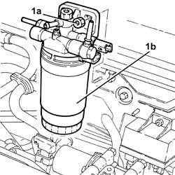
1. Undo the nuts (1a) and remove the fuel filter (1b).
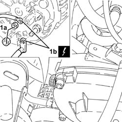
1. Undo the nuts (1a) and disconnect the electrical connections (1b) from the alternator.
| Name | Connector | |
|---|---|---|
| 1b | Alternator | A10 |
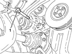
1. Undo the lower alternator fixing bolt.
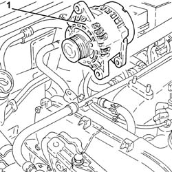
1. Working from the engine bay, remove the the alternator.
Refitting
Refit the alternator in its seating and secure it temporarily with the bottom bolt.
Place the alternator rear mounting bracket back in its housing and secure it using the bolts.
Tighten the two bolts fixing the alternator to the recommended torque.
| Fastening | Component | Ø | Value (daNm) | |
|---|---|---|---|---|
| Lower bolt | ALTERNATOR ASSEMBLY | M12 | 6.0 ÷ 7.4 |
| Fastening | Component | Ø | Value (daNm) | |
|---|---|---|---|---|
| Upper bolt | ALTERNATOR ASSEMBLY | M10 | 4.3 ÷ 5.3 |
Connect the electrical connections to the alternator.
Place the fuel filter back in its housing and secure with the nuts.
Connect the fuel supply pipe to the fuel return manifold, fuel filter side, and secure the corresponding collar.
Connect the quick-release connector for the fuel supply pipe to the pressure pump, fuel filter side.
Connect the quick-release connector for the fuel inlet pipe, fuel filter side.
Connect the electrical connection to the fuel temperature sensor.
Connect the electrical connection to the fuel pre-heating device.
Place the power assisted steering pump pulley protection back in its housing and secure it using the bolts.
Place the guide pipe for the engine oil dipstick back in its housing and fasten the electrical wiring to the bands.
Tighten the upper bolt fixing the engine oil dipstick guide pipe.
Place the engine oil dipstick back in its seating.
Connect the electrical connection for the cam angle sensor and fasten it.
Place the electrical wiring back in its seating and fix it to the bands.
Connect the electrical connection for the air conditioning compressor and secure the electrical wiring to the band.
Connect the front engine coupling.
Connect the electrical connection to the diesel electronic injection control unit.
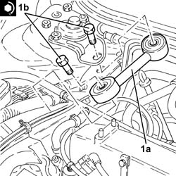
1. Place the power unit reaction rod (1a) back in its housing and fix it tightening the bolts (1b) to the recommended torque.
| Fastening | Component | Ø | Value (daNm) | |
|---|---|---|---|---|
| 1b | Bolt | REACTION ROD | M10 | (Bracket on engine side/bracket on bodyshell) 4.2 ÷ 5.1 |
Tighten the lower bolt fixing the engine oil dipstick guide pipe.
Adjust the moving tensioner and place the engine components single drive belt back in its housing.
Proceed with refitting - 7055B54 under-engine guard - r r.
Proceed with refitting - 7055B91 Right front WHEEL ARCH LINER - R.R..
Proceed with refitting - 4450B04 right front wheel r r.
Proceed with refitting - 1016A10 sound-proofing cover - r + r.
Connect the negative (-) battery terminal.
Remove the car from the ramps.
Removing
Position the vehicle on the ramp.
Proceed with removal - 1016A10 sound-proofing cover - r + r.
Ensure that the ignition key is in the OFF position, then disconnect the negative battery terminal (-).
| Name | Connector | |
|---|---|---|
| Battery | A1B |
Proceed with removal - 4450B04 right front wheel r r.
Proceed with removal - 7055B54 under-engine guard - r r.
Proceed with removal - 7055B91 Right front WHEEL ARCH LINER - R.R..
Proceed with removal - 1092G10 single engine belt r r.
Proceed with removal - 1044B10 fuel filter assembly - r + r or replace.
Proceed with removal - 1080D34 engine oil vapour separator - r + r.
Proceed with removal - 1084A16 oil dip stick pipe - r r.
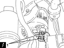
1. Disconnect the electrical connections from the alternator.
| Name | Connector | |
|---|---|---|
| 1 | Alternator | A10 |
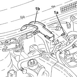
1. Undo the bolts (1a) and remove the power assisted steering pulley protection (1b).
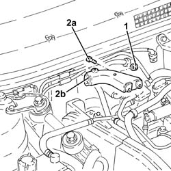
1. Undo the upper alternator fixing bolt.
2. Undo the bolts (2a) and remove the rear alternator bracket (2b).
1. Undo the lower alternator fixing bolt.
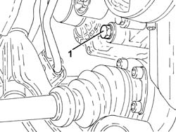
1. Remove the alternator.
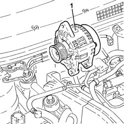
Refitting
Refit the alternator in its seating and secure it temporarily with the bottom bolt.
Place the alternator rear mounting bracket back in its housing and secure it using the bolts.
Tighten the two bolts fixing the alternator to the recommended torque.
| Fastening | Component | Ø | Value (daNm) | |
|---|---|---|---|---|
| Bolt | ALTERNATOR ASSEMBLY | M10 | 4.5 ÷ 5.5 |
| Fastening | Component | Ø | Value (daNm) | |
|---|---|---|---|---|
| Bolt | ALTERNATOR ASSEMBLY | M12 | 6.3 ÷ 7.7 |
Place the power assisted steering pump pulley protection back in its housing and secure it using the bolts.
Connect the electrical connections to the alternator.
Proceed with refitting - 1084A16 oil dip stick pipe - r r.
Proceed with refitting - 1080D34 engine oil vapour separator - r + r.
Proceed with refitting - 1044B10 fuel filter assembly - r + r or replace.
Proceed with refitting - 1092G10 single engine belt r r.
Proceed with refitting - 7055B91 Right front WHEEL ARCH LINER - R.R..
Proceed with refitting - 7055B54 under-engine guard - r r.
Proceed with refitting - 4450B04 right front wheel r r.
Connect the negative (-) battery terminal.
Proceed with refitting - 1016A10 sound-proofing cover - r + r.
Remove the car from the ramps.
Removing
Position the vehicle on the ramp.
Ensure that the ignition key is in the OFF position, then disconnect the negative battery terminal (-).
| Name | Connector | |
|---|---|---|
| Battery | A1B |
Drain the air conditioner coolant circuit - 5040A10 Air conditioning refrigerant CIRCUIT - Draining and Refilling.
Proceed with removal - 4450B04 right front wheel r r.
Proceed with removal - 7055B54 under-engine guard - r r.
Proceed with removal - 7055B64 Engine compartment DUST shield in front wheel arch (one), left or right - R.R..
Proceed with removal - 1092G10 single engine belt r r.
Proceed with removal - 7055B42 Additional FRONT WHEEL ARCH (one), left or right - R.R..
Proceed with removal - 7210E10 R.R. FRONT BUMPER.
Proceed with the removal - 5540B76 Front LIGHT CLUSTER with fog light (one), left or right - R.R. with interfering components removed (Right and left sides).
Proceed with removal - 7025A34 bonnet lid lock (one) - r+r or repair.
Proceed with removal - 7210A15 R.R. HEADLAMP HOUSING/FRONT WING CROSSMEMBER.
Proceed with removal - 1076B82 left exhasust pipe between catalytic preconverter and converter r r.
Proceed with removal - 1076B84 right exhaust pipe between caralytic preconverter and converter r r.
Proceed with removal - 1080B39 right catalytic preconverter r r or replace cylinder head gasket.
Proceed with removal - 4410A80 damper lower fork - r r.
Proceed with removal - 2710A31 intermediate drive shaft - r r.
1. Disconnect the electrical connections from the alternator.
| Name | Connector | |
|---|---|---|
| 1 | Alternator | A10 |
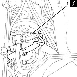
1. Undo the lower alternator fixing bolt.
2. Loosen the upper alternator fixing bolt.
Turn the alternator upwards and lock in position using the upper bolt.
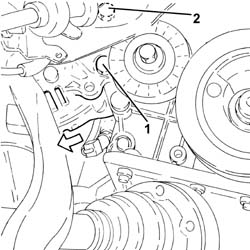
1. Undo the bolt fixing the alternator rear mounting to the cylinder block/crankcase.
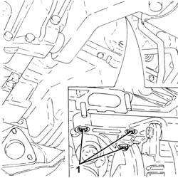
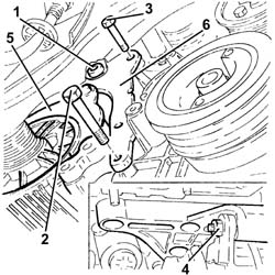
1. Undo the bolt fixing the rear timing belt cover to the alternator spacer.
2. Undo the lower bolt securing the alternator mount spacer bracket to the crankcase.
3. Undo the upper bolt securing the alternator mount spacer bracket to the right cylinder head.
4. Undo the upper alternator fixing bolt.
5. Remove the alternator rear mount.
6. Remove the alternator spacer.
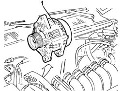
1. Working from the engine bay, remove the the alternator.
Refitting
Refit the alternator.
Assemble the spacer and rear mount to the alternator and secure with the upper bolt, keeping the alternator turned up.
Tighten the bolts fixing the alternator mount spacer bracket.
Tighten the bolt securing the right timing belt cover to the alternator spacer.
Tighten the bolts fixing the alternator rear mounting to the cylinder block/crankcase.
Turn the alternator in place and secure it by tightening the bolts to the recommended torque.
| Fastening | Component | Ø | Value (daNm) | |
|---|---|---|---|---|
| Bolt | OIL SUMP | M6 | (Engine crankcase side/flywheel side oil seal cover) 0.8 ÷ 1.1 |
Connect the electrical connections to the alternator.
Proceed with refitting - 2710A31 intermediate drive shaft - r r.
Proceed with refitting - 4410A80 damper lower fork - r r.
Proceed with refitting - 1080B39 right catalytic preconverter r r or replace cylinder head gasket.
Proceed with refitting - 1076B84 right exhaust pipe between caralytic preconverter and converter r r.
Proceed with refitting - 1076B82 left exhasust pipe between catalytic preconverter and converter r r.
Proceed with refitting - 7210A15 R.R. HEADLAMP HOUSING/FRONT WING CROSSMEMBER.
Proceed with refitting - 7025A34 bonnet lid lock (one) - r+r or repair.
Proceed with the refitting - 5540B76 Front LIGHT CLUSTER with fog light (one), left or right - R.R. with interfering components removed (Right and left sides).
Proceed with refitting - 7210E10 R.R. FRONT BUMPER.
Proceed with refitting - 7055B42 Additional FRONT WHEEL ARCH (one), left or right - R.R..
Proceed with refitting - 1092G10 single engine belt r r.
Proceed with refitting - 7055B64 Engine compartment DUST shield in front wheel arch (one), left or right - R.R..
Proceed with refitting - 7055B54 under-engine guard - r r.
Proceed with refitting - 4450B04 right front wheel r r.
Fill the air conditioner coolant circuit - 5040A10 Air conditioning refrigerant CIRCUIT - Draining and Refilling.
Connect the negative (-) battery terminal.
Remove the car from the ramps.
Parts & tools for this job For 2000 Alfa Romeo 147
- TOOLBattery testerSearch: car battery tester
- TOOLDigital multimeterSearch: automotive digital multimeter
- TOOLBattery terminal cleanerSearch: battery terminal cleaner
Links open Amazon search results in a new tab. As an Amazon Associate I earn from qualifying purchases.