
Vehicle preparation
- Make
- Alfa Romeo
- Model
- GTV / Spider GTV and Spider (916) Factory Service Manual
- Year
- 1995–2000
- Section
- Lighting › Vehicle preparation
Vehicle preparation
The vehicle must be complete with spare wheel, tool kit, oil fluids and fuel, the tyre pressure should be as specified for normal service with the driver on board.
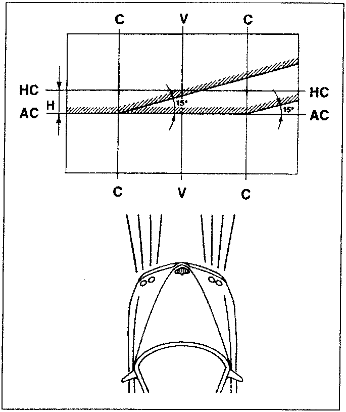
Set the vehicle on a level surface with the headlight cluster glass 10 m from a screen or opaque surface on which the following lines have been traced:
V - V: vertical corresponding to the trace of the plane of symmetry of the vehicle.
C - C: corresponding to the traces of the vertical plaes passig through the centres of reference of the light clusters.
HC - HC: horizontal corresponding to the height from the ground of the centres of reference of the light clusters.
AC - AC: horizontal below line Hc - Hc by 14 cm (value for new cars), 11 cm (value for other than new cars).
Aim the light clusters on the low beam. Acting on the headlamp aiming device as follows.
NOTE: For cars fitted with headlamp aiming device adjust with the device at position "0".
Vertical aiming
Make the horizontal section of the line of demarkation between the dark zone and the illuminated zone coincide with line Ac - Ac traced on the screen.
Horizontal aiming
Make the crossing point of the horizontal and sloping lines of demarkation coincide with the respective crossing point of lines C - C and Ac - Ac of the screen. If the screen needs to be set nearer to the car, this value must be reduced proportionately (eg: if the screen is at half the distance, it must be halved).
LOWER FRONT LIGHT CLUSTERS
REMOVAL/REFITTING
- Disconnect the battery.
- Remove the triangular trim.
- Slacken the two screws.
- Remove the light cluster releasing the outer pin.
- Disconnect the electrical connections and remove the light cluster.
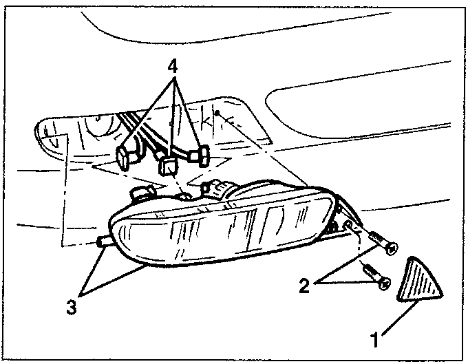
- Outer trim
- Screws
- Light cluster
- Mounting bracket
Parts & tools for this job For 1995 Alfa Romeo GTV / Spider
- PARTReplacement bulbsSearch: Alfa Romeo GTV / Spider 1995 bulbs
- TOOLDigital multimeterSearch: automotive digital multimeter
Links open Amazon search results in a new tab. As an Amazon Associate I earn from qualifying purchases.