
Description (page 6 of 10)
- Make
- Alfa Romeo
- Model
- GTV / Spider GTV and Spider (916) Factory Service Manual
- Year
- 1995–2000
- Section
- Removal/Refitting
Variants – 2.0 V6 Turbo (GTV and Spider)Description · page 6 of 10
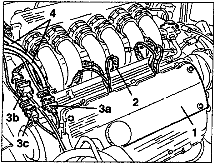
- Slacken the four fastening screws and remove the lefthand cylinder head cover.
- Disconnect the electrical connections from the injectors.
- Disconnect the electrical connections (3a) of the rpm and timing sensor, (3b) pinging sensors and (3c) lambda sensor, then move the wiring to one side.
- Disconnect the two fuel inlet and outlet pipes from the distributor manifold.
- Disconnect the earth cables from the intake box.
- Slacken the fastening screws and remove the engine stay connecting rod.
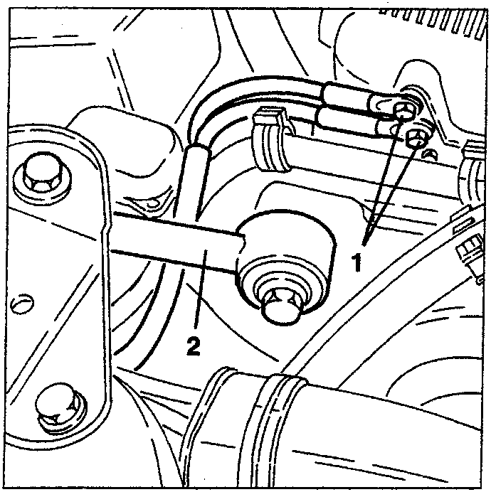
- Slacken the fastening screw and remove the earth cables support bracket from the intake box.
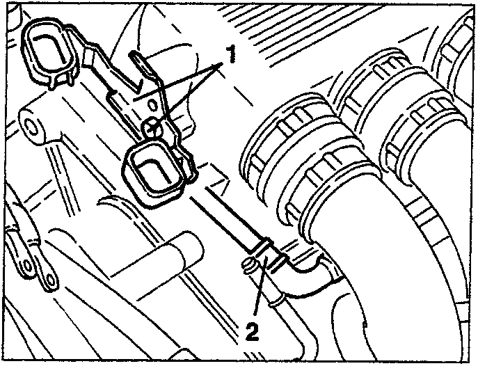
- Disconnect the fuel vapour recirculation pipe from the fuel distributor manifold.
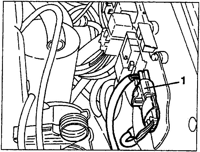
- Remove the protective cover, then disconnect the electrical connection for energizing the starter motor, of the low battery charge warning light and of the minimum engine pressure warning light.
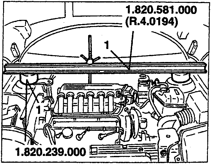
- Install crossrail no.1.820.581.000 (R.4.0194) complete with supports no. 1.820.239.000 to support the power unit.
WARNING: Interpose suitable thicknesses between the crossrail and the side panel.
Parts & tools for this job For 1995 Alfa Romeo GTV / Spider
- TOOLTorque wrenchSearch: 3/8 inch torque wrench
- TOOLSocket setSearch: socket set metric
- BOOKHaynes manualSearch: Haynes manual Alfa Romeo GTV / Spider
Links open Amazon search results in a new tab. As an Amazon Associate I earn from qualifying purchases.