
Maintenance (page 4 of 12)
- Make
- Alfa Romeo
- Model
- GTV / Spider GTV and Spider (916) Factory Service Manual
- Year
- 1995–2000
- Section
- Maintenance
Variants – 3.0 V6 24VMaintenance · page 4 of 12
- Disconnect the coolant fluid inlet pipe from the throttle body.
- Disconnect the vacuum takeoff pipe for the E.G.R. modulating valve from the intake box.
- Disconnect the vacuum takeoff pipe for the fuel pressure regulator from the intake box.
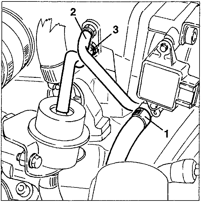
- Throttle body
- E.G.R. modulating valve pipe
- Fuel pressure regulator pipe
- Disconnect the earth cable (rear) from the intake box.
- Slacken the two fastening screws and remove the complete intake box.
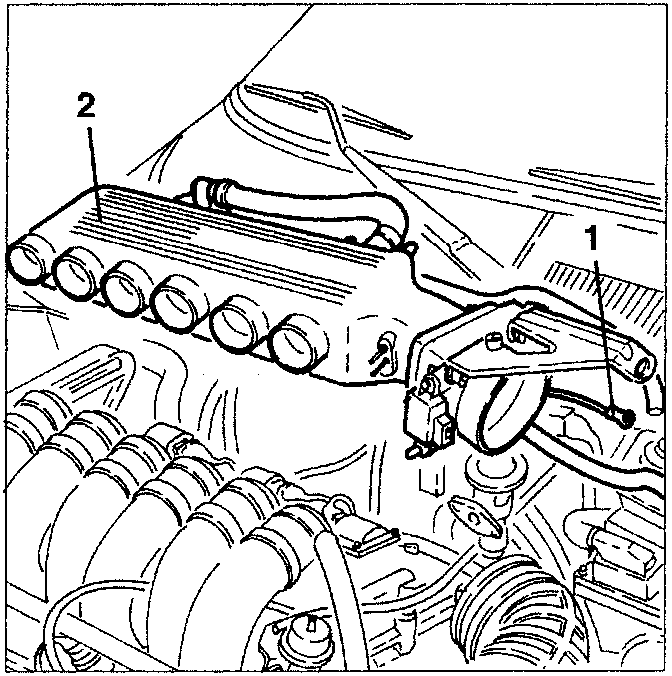
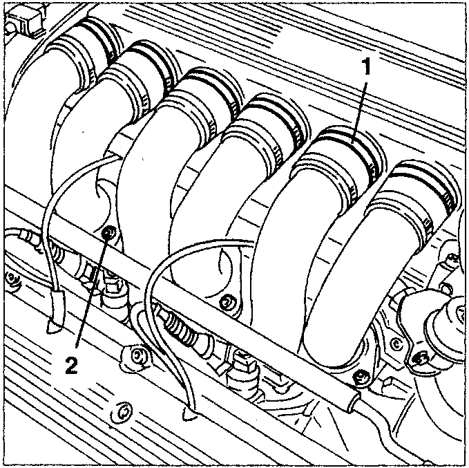
- Slacken the clamps fastening the air supply ducts to the intake box.
- Slacken the fastening screws of the cylinder head supply ducts.
- If necessary, on the bench separate the throttle body (1a), the oil vapour separator (1b) and the constant idle actuator (1c).
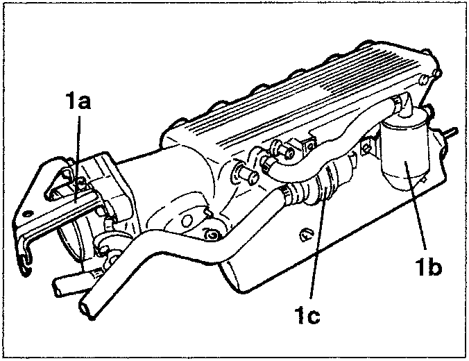
- Throttle body
- Oil vapour separator
- Constant idle actuator
Parts & tools for this job For 1995 Alfa Romeo GTV / Spider
- PARTOil filterSearch: Alfa Romeo GTV / Spider 1995 oil filter
- TOOLOil filter wrenchSearch: oil filter wrench
- FLUIDEngine oilSearch: Alfa Romeo GTV / Spider engine oil
Links open Amazon search results in a new tab. As an Amazon Associate I earn from qualifying purchases.