
Evaporative Loss System
- Make
- Aston Martin
- Model
- DB9 Factory Workshop Manual
- Year
- Issue 2, 2005
- Section
- Fuel Tank and Lines › Evaporative Loss System
It includes the positive crankcase ventilation and vapour recovery systems.
- Oil separator
- PCV valve
- Check valve
- Relief valve
- Vapour management valve
- Fuel tank pressure transducer
- Carbon canister
- Canister vent valve
- Fuel limit vent valve
- Test port
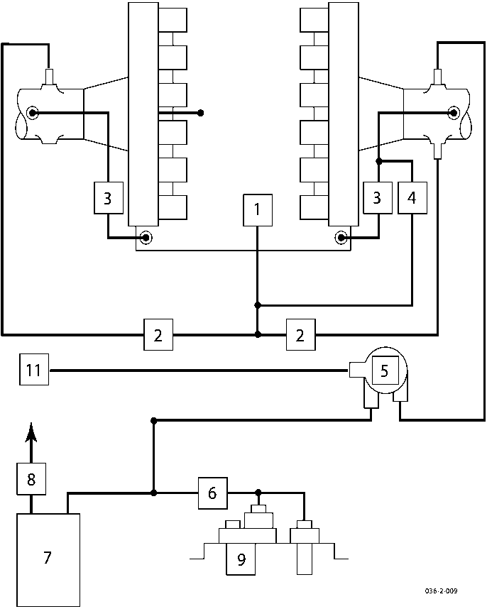
Evaporative Loss System
Fuel vapour is displaced from the fuel tank during filling. Vapour is also displaced due to fuel evaporation in higher temperatures. Displaced fuel vapour is absorbed in the carbon canister filter located on top of the fuel tank.
During normal engine running, absorbed fuel vapour is purged from the carbon canisters and mixed with the normal fuel/air charge in the inlet manifold.
System Operation
Displaced fuel vapour leaves the fuel tank via the normally open fuel level vent valve and the roll over valves. It passes through the carbon canister where fuel hydrocarbons are absorbed. Clean air leaves the system via the normally open canister vent valve. This valve is only closed during diagnostic pressure testing of the fuel system.
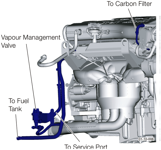
During normal engine running, the single vapour management valve in the engine bay is periodically opened, when negative pressure exists in the intake manifold, allowing fresh air flow into the open canister vent valve, through the carbon canister, through the vapour management valve and into the primary inlet manifold. This fresh air flow progressively purges any absorbed fuel vapour from the carbon canister.
Fuel Tank Vents and Control Valves
Parts & tools for this job For 2005 Aston Martin DB9
- TOOLTorque wrenchSearch: 3/8 inch torque wrench
- TOOLSocket setSearch: socket set metric
- BOOKHaynes manualSearch: Haynes manual Aston Martin DB9
Links open Amazon search results in a new tab. As an Amazon Associate I earn from qualifying purchases.