
Abs check/adjustment devices
- Make
- Fiat
- Model
- 500 Factory Service Manual
- Year
- 2007–2024
- Section
- Anti-lock braking system – ABS › Abs check/adjustment devices
ABS CHECK/ADJUSTMENT DEVICES
DESCRIPTION OF COMPONENTS
Electrohydraulic unit
The unit consists of an electronic control unit (1) and an electro-hydraulic control unit (2).
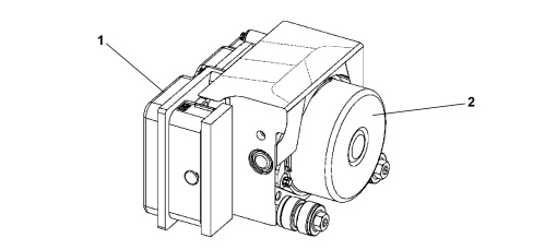
Electronic control unit
The electronic control unit carries out the following functions:
- acquiring the data coming from the wheel rpm sensors,
- memorising the control parameters defined during the vehicle P.D.I.,
- memorizing the software,
- processing the data acquired,
- controlling the braking process,
- detecting faults in the ABS components,
- memorizing the fault codes and activating the ABS and EBD warning lights,
- transmitting and receiving data via the C-CAN line,
- transmitting and receiving data via the diagnostic connector.
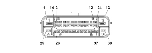
| ABS control unit pin out | |
|---|---|
| Pin | Function |
| 1 | + 30 |
| 2 | n.c. |
| 3 | n.c. |
| 4 | n.c. |
| 5 | n.c. |
| 6 | Right-hand front wheel sensor signal K071 |
| 7 | n.c. |
| 8 | n.c. |
| 9 | n.c. |
| 10 | n.c. |
| 11 | n.c. |
| 12 | n.c. |
| 13 | Earth |
| 14 | C CAN ( L ) |
| 15 | C CAN ( L ) |
| 16 | Vehicle speed signal (n.c.) |
| 17 | K line (n.c.) |
| 18 | Right-hand front wheel sensor power supply K071 |
| 19 | Right-hand rear wheel sensor power supply K076 |
| 20 | Left-hand rear wheel sensor signal K075 |
| 21 | n.c. |
| 22 | Left-hand front wheel sensor signal K070 |
| 23 | n.c. |
| 24 | n.c. |
| 25 | + 30 |
| 26 | C CAN ( H ) |
| 27 | C CAN ( H ) |
| 28 | n.c. |
| 29 | n.c. |
| 30 | n.c. |
| 31 | Right-hand rear wheel sensor signal K076 |
| 32 | + 15 |
| 33 | Left-hand rear wheel sensor power supply K075 |
| 34 | Left-hand front wheel sensor power supply K070 |
| 35 | n.c. |
| 36 | n.c. |
| 37 | n.c. |
| 38 | Earth |
Hydraulic control unit
It performs the function of modulating the pressure of the fluid at the brake callipers via solenoids, with the following operating stages:
- brake fluid pressure increase,
- brake fluid pressure maintenance,
- brake fluid pressure decrease.
For more details see:
See descriptions 3340 ANTI-LOCK BRAKING SYSTEM (ABS)
The hydraulic control unit consists of:
- eight 2-way solenoid valves,
- a dual circuit scavenging pump,
- two low pressure accumulators,
- two high pressure accumulators.
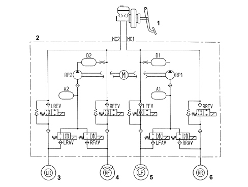
1. Brake servo brake pump assembly
2. Hydraulic control unit
3. Left rear wheel
4. Right front wheel
5. Left front wheel
6. Right rear wheel
Active sensors
Specifications
The adoption of active sensors offers the following advantages:
- less sensitivity to the distance between the sensor and the magnetic ring (gap),
- a reduction in sensitivity to electro-magnetic interference,
- the capacity of the active sensor to measure wheel rpm speeds down to zero (instead of 2.5 km/h for passive sensors),
- a saving in weight and size,
- a simplification of the transmission couplings through the elimination of the phonic wheels.
Structure
Active sensors consist of two fundamental components:
- a multipolar magnetic coding device (1) incorporated in the wheel hub bearing
- a Hall effect receiver (2) that faces the coding device.
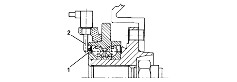
The active sensor functions on the basis of variation in the internal electrical resistance, according to the intensity and direction of the lines of force of an external magnetic field (multipolar magnetic coding device). It produces a variable square wave signal whose frequency varies according to the rotation speed of the wheel, but has a constant amplitude.
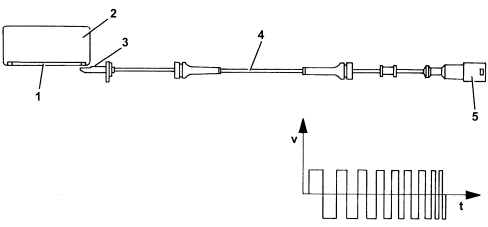
1. Magnetised sealing ring
2. Bearing
3. Sensor head
4. Active sensor
5. Sealed connector
The active sensor is therefore a proximity sensor with built-in electronic system, connected by means of a cable to the ABS control unit, from which it receives an electrical supply and to which it transmits the speed of the vehicle.
The phonic wheel is a multipolar ring, an elastomer with a certain amount of magnetic particles which are aligned to form different magnets with alternating North / South polarity in a circumferential arrangement by means of a special magnetisation technique. 48 negative poles and 48 positive poles are present in total.
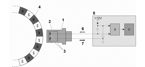
1. Receiver
2. Hall sensor
3. Sensitive elements
4. Multipolar magnetic codifier
5. ABS control unit
6. Sensor power supply
7. Sensor signal
8. Square wave signal generator
9. ABS control unit processor
Parts & tools for this job For 2007 Fiat 500
- TOOLOBD2 scanner with ABSSearch: OBD2 scanner ABS SRS
- TOOLDigital multimeterSearch: automotive digital multimeter
Links open Amazon search results in a new tab. As an Amazon Associate I earn from qualifying purchases.