
Ignition switch assembly - r+r
- Make
- Fiat
- Model
- Bravo Factory Service Manual
- Year
- 2007–2014
- Section
- Engine starting › Ignition switch assembly - r+r
IGNITION SWITCH ASSEMBLY - R+R
Removing
Op. 7040A26 STEERING COLUMN TRIM - R+R
Op. 5580E08 AERIAL FOR ELECTRONIC KEY (CODE) - R.R
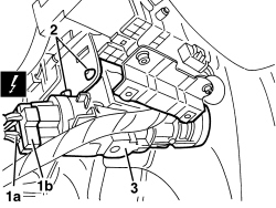
1. Detach electrical connections (1a, 1b).
| Description | Connector | |
|---|---|---|
| 1 | IGNITION SWITCH | See H001 IGNITION SWITCH |
2. Remove the shear bolts using a drift and mallet.
3. Remove the complete ignition switch.
Work carefully to avoid striking the Air Bag or creating excessive vibrations.
If necessary, separate the lock barrel
Op. 5520A14 IGNITION KEY LOCK BARREL - R+R
Refitting
- Check that the ignition switch is not damaged.
Op. 5520A14 IGNITION KEY LOCK BARREL - R+R
- Place the ignition switch in position.
- Screw in and tighten the new special bolts until the heads shear off.
- Connect the electrical connections.
Op. 5580E08 AERIAL FOR ELECTRONIC KEY (CODE) - R.R
Op. 7040A26 STEERING COLUMN TRIM - R+R
- Check the operation of the ignition and steering lock.
Parts & tools for this job For 2007 Fiat Bravo
- TOOLOBD2 scannerSearch: OBD2 scanner
- TOOLDigital multimeterSearch: automotive digital multimeter
- TOOLBack-probe test leadsSearch: back probe test leads
Links open Amazon search results in a new tab. As an Amazon Associate I earn from qualifying purchases.