
Lambda adjustment (page 2 of 2)
- Make
- Fiat
- Model
- Bravo /Brava (182) Factory Service Manual
- Year
- 1995–2001
- Section
- Fuel system (1370 12v)
The ignition system is solid-state distribution type. In other words, moving parts are eliminated by doing away with a high tension distributor (case-brush-cap).
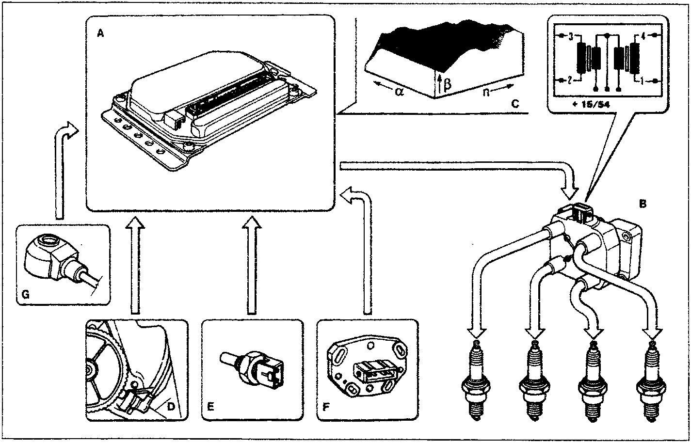
Coil (B) is fitted with four high tension outlets connected directly to the spark plugs. Their operation is managed entirely by control unit (A).
The control unit contains (in addition to fuel metering control parameters) a memory map (C) containing a set of optimal advance angles that can be used by the engine according to service conditions: engine load (α) and rpm (n).
The mapped values are obtained experimentally on a bench taking into account power, fuel consumption and polluting emissions.
The control unit selects the appropriate advance value according to the memory maps, rpm (D), coolant temperature (E) and engine load (F), knock (G) and governs the ignition unit power module accordingly.
The control unit contains three different base advance angle maps to cater for changing engine service conditions:
- full load, settings mapped according to rpm and engine load.
- partial load, settings again mapped according to rpm and engine load.
- idling, where settings are mapped according to rpm.
The full load and partial load advance angle may also be subject to further corrections on the basis of engine temperature and air temperature. The idle advance angle is corrected only on the basis of engine temperature (non-constant value is about 7°).
The control unit contains an algorithm that computes the advance on the basis of rpm and battery voltage at which current begins to flow into the coil primary winding.
Parts & tools for this job For 1995 Fiat Bravo
- PARTOxygen sensorSearch: Fiat Bravo 1995 oxygen sensor
- TOOLOxygen sensor socketSearch: oxygen sensor socket
- TOOLOBD2 scannerSearch: OBD2 scanner
Links open Amazon search results in a new tab. As an Amazon Associate I earn from qualifying purchases.