
Alarm
- Make
- Fiat
- Model
- Bravo /Brava (182) Factory Service Manual
- Year
- 1995–2001
- Section
- Alarm › Alarm
55 Electrical systemAlarm · page 1 of 2
Alarm
INPUT AND OUTPUT SIGNALS FROM THE ANTI-THEFT DEVICE CONTROL UNIT
| PIN | I/O | I Max (A) | FUNCTION |
|---|---|---|---|
| B1 | OUT | 6 | Relay n.a. contact: right direction indicators operation |
| B2 | OUT | 6 | Relay n.a. contact: left direction indicators operation |
| B3 | OUT | 8 | Preparation for relay n.c. contat: inhibition of diesel pump electrostop + heater plugs / +15 injection wiring / petrol pump |
| B4 | IN | 8 | Preparation for relay n.c. contact: +15 for B3 |
| B5 | OUT | 8 | Preparation for relay n.c. contact: outlet +50 starter motor supply |
| B6 | IN | 8 | Preparation for relay n.c. contact: +50 for B5 and B10 |
| B7 | IN | 12 | Direction indicators relay common contact: +30 direction indicators supply |
| B8 | IN | * | Left front door open (=closed) switch |
| B9 | IN | * | Right front door open (=closed) switch |
| B10 | OUT | 0,04 | Preparation for two coloured LED operation |
| B11 | IN | 0,04 | Preparation required for operating two coloured LED by Fiat CODE |
| B12 | IN | 2 | Positive controlled by the ignition (+15) |
| B13 | IN | * | Remote key: common |
| B14 | OUT | 0,3 | Operation of check: signalling door/s open |
| B15 | IN | * | Switch signalling left rear door open (=closed) |
| B16 | IN | * | Switch signalling right rear door open (=closed) |
| B17 | IN | * | Switch signalling boot lid open (=closed) |
| B18 | IN | * | Switch signalling bonnet lid open (=closed) |
| A1 | OUT | 0,04 | Operation of (two coloured) LED flashing |
| A2 | I/O | * | VAS serial line from courtesy light |
| A3 | IN | * | Direct positive supply (+30) |
| A4 | IN | * | Remote key: internal supply |
| A5 | OUT | 0,03 | Anti-lifting modules positive supply |
| A6 | I/O | * | Line K-Fiat tester |
| A7 | OUT | * | Remote key: external supply |
| A8 | OUT | 0,03 | Volumetric modules supply positive |
| A9 | IN | 2 | VAS control unit earth |
| A10 | I/O | * | Preparation for serial line (supply control unit) |
| A11 | OUT | 0,06 | External modules earth |
| A12 | IN | * | Alarm signal from external modules (low = alarm) |
* Signal current > 0,3 mA, < 10mA.
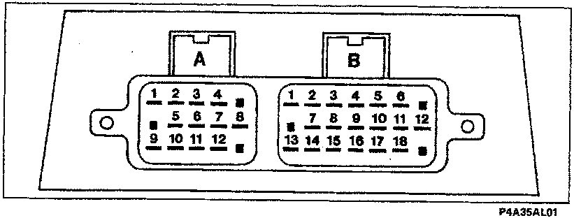
Alarm control unit input and output signals
Parts & tools for this job For 1995 Fiat Bravo
- TOOLDigital multimeterSearch: automotive digital multimeter
- PARTAssorted fuse kitSearch: car fuse assortment kit
- TOOLWire crimper and connector kitSearch: wire crimper connector kit
Links open Amazon search results in a new tab. As an Amazon Associate I earn from qualifying purchases.