
Receiver connector
- Make
- Fiat
- Model
- Bravo /Brava (182) Factory Service Manual
- Year
- 1995–2001
- Section
- Alarm › Receiver connector
55 Electrical systemReceiver connector
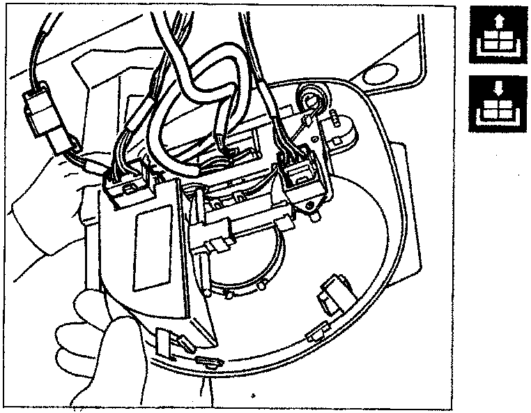
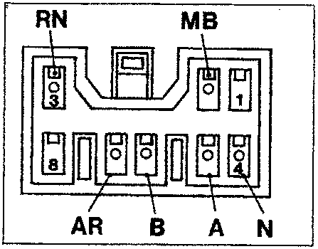
RECEIVER CONNECTOR
The receiver is a module housed in the roof of the vehicle behind the courtesy light, which- has an 8 way connector with the following connections:
- Not connected
- Serial line towards the anti-theft device
- Positive from battery (+30)
- Earth
- Command to central locking to unlock
- Command to central locking to lock
- Positive from ignition switch (+15)
- Not connected
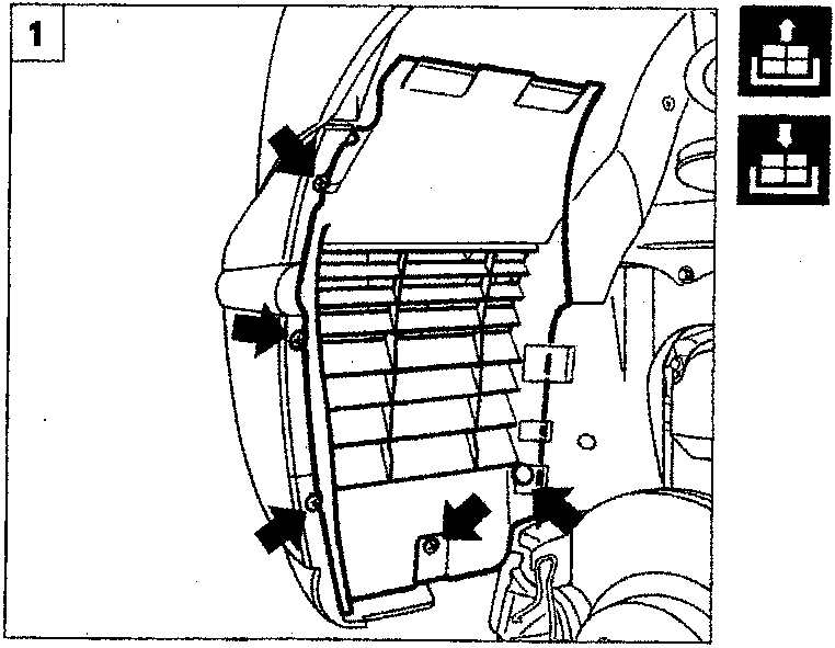
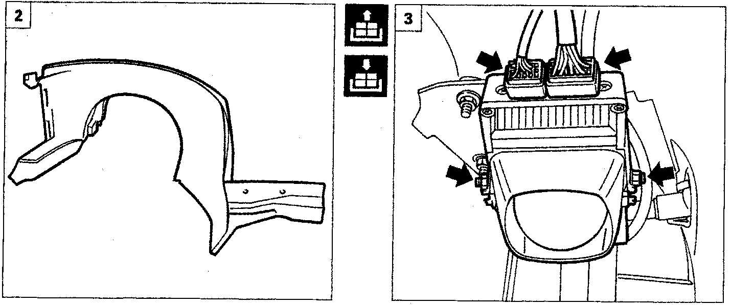
REMOVING-REFITTING ALARM CON- TROL UNIT
Position the vehicle on a lift and remove the left wheel.
- Undo the fixing bolts and remove the front section of the wheel arch liner.
- Undo the fixing bolts and remove the re- maining part of the wheel arch liner.
- Disconnect the electrical connections, undo the nuts shown and remove the alarm control unit from the vehicle.
Parts & tools for this job For 1995 Fiat Bravo
- TOOLDigital multimeterSearch: automotive digital multimeter
- PARTAssorted fuse kitSearch: car fuse assortment kit
- TOOLWire crimper and connector kitSearch: wire crimper connector kit
Links open Amazon search results in a new tab. As an Amazon Associate I earn from qualifying purchases.