
Brake servo/brake pump assembly - r.r.
- Make
- Fiat
- Model
- Croma Factory Service Manual
- Year
- 2005–2010
- Section
- Hydraulic brake system › Brake servo/brake pump assembly - r.r.
BRAKE SERVO/BRAKE PUMP ASSEMBLY - R.R.
Removing
Op. 5530B52 BATTERY SUPPORT/DRIP TRAY - R.R
Op. 7040A24 LOWER FACIA COVER TRIM - R+R
Op. 7040A26 STEERING COLUMN TRIM - R+R
Op. 7040A44 LEFT DASHBOARD SIDE TRIM - R.R.
Op. 5010C57 LEFT LOWER AIR DIFFUSER - R R
Op. 5580C23 DRIVE SIDE KNEE PROTECTION AIR BAG MODULE R. R.
Follow all the recommended safety instructions (see 5580C - Precautions).
Op. 7040A30 LEFT LOWER DASHBOARD TRIM - R.R.
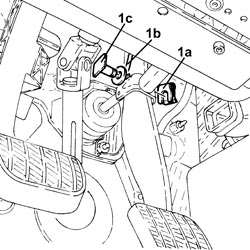
1. Remove the retaining clip (1a), release the return spring (1b) and extract the pin (1c) connecting the brake servo to the brake pedal.
- Replace the brake-clutch fluid reservoir plug using the tool.
| Tool | Description | Function | Validity |
|---|---|---|---|
| 2000001400 | Plug | Brake/clutch fluid reservoir cap |
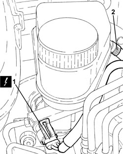
1. Disconnect the electrical connection from the minimum brake fluid level warning light switch.
| Description | Connector | |
|---|---|---|
| 1 | Brake fluid level sensor (switch) | See K025 BRAKE FLUID LEVEL SENSOR (SWITCH) |
2. Loosen the band and disconnect the pipe from the clutch reservoir to the master cylinder, reservoir side.
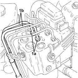
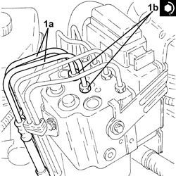
1. Undo the connectors (1a) and disconnect the pipes from the master cylinder to the electro-hydraulic control unit (1b), electro-hydraulic control unit side.
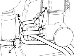
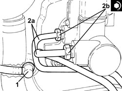
1. Undo the connectors (1a), disconnect the pipes from the master cylinder to the electro-hydraulic control unit (1b), master cylinder side and remove them.
2. Disconnect the single-acting valve from the brake servo.
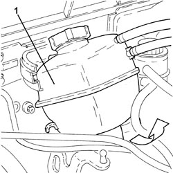
1. Rotate the engine coolant supply reservoir as illustrated in the diagram, then remove it.
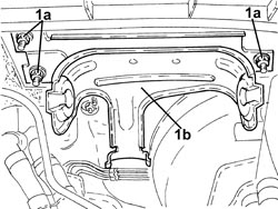
1. Undo the nuts (1a) and remove the engine coolant supply reservoir mounting bracket (1b).
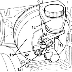
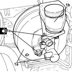
1. Undo the bolts (1a) and remove the brake servo/brake pump (1b) complete with the reservoir (1c).
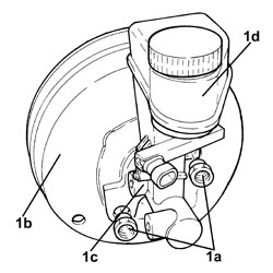
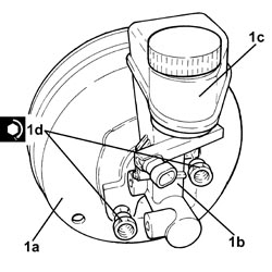
1. At the bench, undo the nuts (1a) and separate the brake servo (1b) from the brake master cylinder (1c) complete with reservoir (1d).
Refitting
- Clean the surface of the brake servo and the engine compartment bulkhead.
- Replace the seal on the brake master cylinder.
Do not use mineral oils or grease.
1. Assemble the brake servo (1a) and the brake master cylinder (1b) complete with reservoir (1c) and tighten the nuts (1d) to the recommended torque.
| Component | Fastening | dia | Value (daNm) | Validity |
|---|---|---|---|---|
| Master cylinder brake (pump) | Nut (to replace) | (brake servo side) 2.1 - 2.9 |
1. Place the bearing cap (1a) in its seat complete with half-bearing (1b) and secure it by tightening the bolts (1c) to the recommended torque.
| Component | Fastening | dia | Value (daNm) | Validity |
|---|---|---|---|---|
| Brake servo | Bolt | M8 | (pedals side) 1.8 - 2.2 |
- Place the engine coolant reservoir mounting bracket in its housing and secure it using the nuts.
- Place the engine coolant supply reservoir in its housing.
1. Connect the single-acting valve to the brake servo.
2. Place the pipes from the master cylinder to the electro-hydraulic (2a) in their housing, connect them to the master cylinder and tighten the connectors (2b) to the recommended torque.
| Component | Fastening | dia | Value (daNm) | Validity |
|---|---|---|---|---|
| Brake pipe connectors | Connector | M10/M12 | 1.4 ÷ 1.8 |
1. Connect the pipes from the master cylinder to the electro-hydraulic control unit (1a), electro-hydraulic control unit side and tighten the connectors (1b) to the recommended torque.
| Component | Fastening | dia | Value (daNm) | Validity |
|---|---|---|---|---|
| Brake pipe connectors | Connector | M10/M12 | 1.4 ÷ 1.8 |
- Connect the pipe from the clutch reservoir to the master cylinder, reservoir side and tighten the band.
- Connect the electrical connection to the brake fluid minimum level warning light switch.
- Replace the brake-clutch fluid reservoir plug using the tool.
| Tool | Description | Function | Validity |
|---|---|---|---|
| 2000001400 | Plug | Brake/clutch fluid reservoir cap |
- Place the pin connecting the brake servo to the brake pedal in its housing, connect the return spring and fit the retaining clip.
Op. 7040A30 LEFT LOWER DASHBOARD TRIM - R.R.
Op. 5580C23 DRIVE SIDE KNEE PROTECTION AIR BAG MODULE R. R.
Op. 5010C57 LEFT LOWER AIR DIFFUSER - R R
Op. 7040A44 LEFT DASHBOARD SIDE TRIM - R.R.
Op. 7040A26 STEERING COLUMN TRIM - R+R
Op. 7040A24 LOWER FACIA COVER TRIM - R+R
Op. 5530B52 BATTERY SUPPORT/DRIP TRAY - R.R
Op. 0010T64 BRAKE AND/OR CLUTCH FLUID CHECK LEVEL AND TOP UP AS NECESSARY
Parts & tools for this job For 2005 Fiat Croma
- PARTBrake padsSearch: Fiat Croma 2005 brake pads
- TOOLBrake bleeder kitSearch: one man brake bleeder kit
- FLUIDBrake fluidSearch: brake fluid
Links open Amazon search results in a new tab. As an Amazon Associate I earn from qualifying purchases.