
Introduction - fuel tank and pipes
- Make
- Fiat
- Model
- Croma Factory Service Manual
- Year
- 2005–2010
- Section
- Fuel tank and pipes › Introduction - fuel tank and pipes
INTRODUCTION - FUEL TANK AND PIPES
FUEL SUPPLY SYSTEM
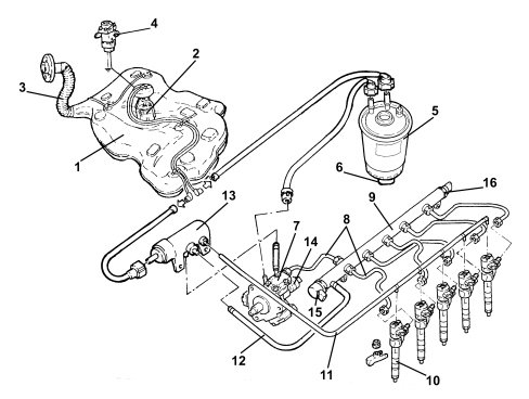
1 - Fuel tank
2 - Submerged fuel assembly complete with level gauge control
3 - Fuel filler pipe
4 - Inertia switch
5 - Fuel filter filter element
6 - Water in fuel filter sensor
7 - Pressure pump
8 - High pressure pipes
9 - Single fuel manifold pipe (rail)
10 - Injectors
11 - Pipe from injectors to fuel return manifold pipe
12 - Return pipe from rail to fuel return manifold pipe
13 - Fuel return manifold pipe
14 - Fuel pressure regulator on pump
15 - Fuel pressure regulator on rail
16 - Fuel pressure sensor
CONSTRUCTION SPECIFICATIONS
This fuel injection system uses an electronically controlled high injection pressure and a fuel supply method produced by one main injection and one or two pilot injections (depending on the engine operating conditions), electronically controlled by the injection control unit via the injector.
Pressure level is the basic parameter for optimising fuel consumption and exhaust fume levels.
The pilot injections make it possible to preheat the combustion chamber to avoid the pressure peak caused by rapid combustion and ensure smoother running.
Injection pressure regulation is made possible by the constructional features of the system, which is equipped with separate pressure pump and injectors, both managed by a control unit. In this way, injection pressure is independent of engine rotation speed.
The main features of the fuel feed system are as follows:
- high injection pressure (up to 1400 bar);
- injection pressure that can be modulated from 150 to 1400 bar under all engine operating conditions
- introduction of fuel up to 100 mm³/cycle within a speed range of 100 to 6000 rpm;
- precise injection control in terms of advance and duration;
- one or two pilot injections before TDC managed on the basis of rpm and engine load that allow the pressure in the combustion chamber to be distributed more evenly with a reduction in noise levels.
COMPOSITION
The fuel system is divided into a low pressure circuit and a high pressure circuit.
The low pressure circuit consists of:
- an auxiliary pump submerged in the tank;
- the fuel filter;
- the fuel return manifold pipe;
- the connecting pipes.
The high pressure circuit consists of:
- the pressure pump;
- the single fuel manifold pipe;
- the injectors;
- the connecting pipes.
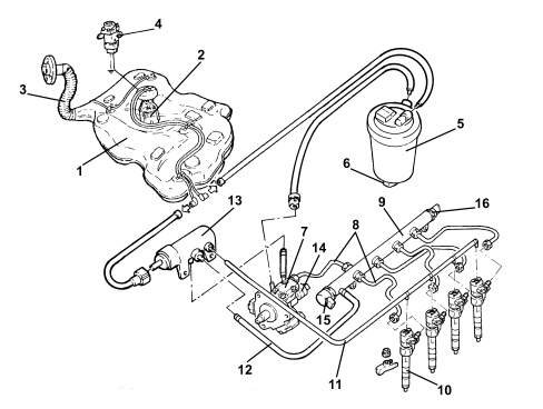
1 - Fuel tank
2 - Submerged fuel assembly complete with level gauge control
3 - Fuel filler pipe
4 - Inertia switch
5 - Fuel filter filter element
6 - Water in fuel filter sensor
7 - Pressure pump
8 - High pressure pipes
9 - Single fuel manifold pipe (rail)
10 - Injectors
11 - Pipe from injectors to fuel return manifold pipe
12 - Return pipe from rail to fuel return manifold pipe
13 - Fuel return manifold pipe
14 - Fuel pressure regulator on pump
15 - Fuel pressure regulator on rail
16 - Fuel pressure sensor
CONSTRUCTION SPECIFICATIONS
This fuel injection system used a high injection pressure under electronic control and a fuel delivery method known as a pilot injection that is electronically controlled by the electronic injection system via the injector (instead of being controlled by the injection pump as in previous direct injection engines).
Pressure level is the basic parameter for optimising fuel consumption and exhaust fume levels.
A pilot injection makes it possible to preheat the combustion chamber to avoid the pressure peak causd by rapid combustiojn and ensure smoother running.
Injection pressure regulation is made possible by the constructional features of the system, which is equipped with separate pressure pump and injectors, both managed by a control unit. In this way, injection pressure is independent of engine rotation speed.
The main features of the fuel feed system are as follows:
- high injection pressure (up to 1350 bar);
- injection pressure that can be modulated from 150 to 1350 bar under all engine operating conditions
- introduction of fuel up to 100 mm³/cycle within a speed range of 100 to 6000 rpm;
- precise injection control in terms of advance and duration;
- a pilot injection before TDC managed on the basis of rpm and engine load that allows pressure drift in the combustion chamber to be reduced to lower noise levels.
COMPOSITION
The fuel system is divided into a low pressure circuit and a high pressure circuit.
The low pressure circuit consists of:
- an auxiliary pump submerged in the tank;
- the fuel filter;
- the fuel return manifold pipe;
- the connecting pipes.
The high pressure circuit consists of:
- the pressure pump;
- the single fuel manifold pipe;
- the injectors;
- the connecting pipes.
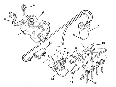
1 - Fuel tank
2 - Submerged fuel assembly complete with level gauge control
3 - Fuel filler pipe
4 - Inertia switch
5 - Fuel filter filter element
6 - Water in fuel filter sensor
7 - Pressure pump
8 - High pressure pipes
9 - Single fuel manifold pipe (rail)
10 - Injectors
11 - Pipe from injectors to fuel return manifold pipe
12 - Return pipe from rail to fuel return manifold pipe
13 - Fuel return manifold pipe
14 - Fuel pressure regulator on pump
15 - Fuel pressure sensor
SPECIFICATIONS
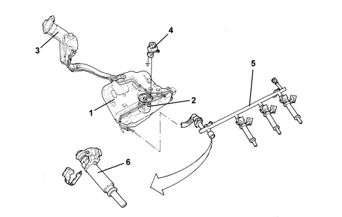
The fuel supply system is the returnless type, i.e. with a single connecting pipe between the fuel tank and the engine.
This makes it possible to:
- minimize the possibility of the vehicle catching fire in case of an accident.
- reduce fuel vapour emissions to the atmosphere.
The fuel tank is located in front of the rear axle. It is made out of plastic with high mechanical strength.
The fuel pump is enclosed in the cradle that also incorporates:
- the fuel pressure regulator
- the fuel level gauge
- the fuel filter.
The system is equiped with an inertia switch that cuts off the fuel supply from the fuel pump if the vehicle crashes.
Fuel supply system
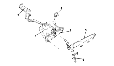
1. Fuel tank
2. Submerged fuel assembly complete with level gauge control
3. Fuel filler pipe
4. Inertia switch
5. Fuel distribution manifold
6. Injectors
SPECIFICATIONS
The fuel supply system is the returnless type, i.e. with a single connecting pipe between the fuel tank and the engine.
This makes it possible to:
- minimize the possibility of the vehicle catching fire in case of an accident.
- reduce fuel vapour emissions to the atmosphere.
The fuel tank is located in front of the rear axle. It is made out of plastic with high mechanical strength.
The fuel pump is enclosed in the cradle that also incorporates:
- the pressure regulator
- the level gauge
- the filter.
1. Fuel tank
2. Submerged fuel assembly complete with level gauge control
3. Fuel filler pipe
4. Inertia switch
5. Fuel distribution manifold
6. Injector
Parts & tools for this job For 2005 Fiat Croma
- PARTEngine gasket setSearch: Fiat Croma 2005 engine gasket set
- TOOLTorque wrenchSearch: 3/8 inch torque wrench
- TOOLFeeler gauge setSearch: feeler gauge set
Links open Amazon search results in a new tab. As an Amazon Associate I earn from qualifying purchases.