
Fuel tank - r + r and decant fuel
- Make
- Fiat
- Model
- Croma Factory Service Manual
- Year
- 2005–2010
- Section
- Fuel tank and pipes › Fuel tank - r + r and decant fuel
FUEL TANK - R + R AND DECANT FUEL
Removing
- Position the vehicle on a lift.
- Make sure that the ignition key is in the OFF position, then disconnect the battery terminal (-).
| Description | Connector | |
|---|---|---|
| Battery | See A001 BATTERY |
Op. 4450B08 RIGHT REAR WHEEL - R.R
Op. 7055B45 RIGHT REAR WHEEL ARCH LINER - R.R
Op. 1040A30 FUEL FILLER PIPE ASSEMBLY- R + R
Op. 1076B20 REAR EXHAUST SILENCER - R + R
Op. 1076B30 FRONT EXHAUST SILENCER - R + R
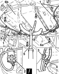
1. Release the handbrake control cables from the intermediate fastenings.
2. Disconnect the intermediate electrical connection for the electrical wiring for the submerged fuel pump assembly complete with fuel gauge.
| Description | Connector | |
|---|---|---|
| 2 | Fuel pump and level gauge | See N040 FUEL PUMP AND LEVEL GAUGE |
3. Disconnect the rapid connector for the rear fuel supply pipe, intermediate fuel supply pipe side.
4. Disconnect the rapid connector for the fuel vapour pipe.
5. Position a hydraulic jack with a suitable tool for supporting the fuel tank.
6. Undo the bolts (6a), lower the hydraulic jack and remove the fuel tank assembly (6b).
Refitting
- Place the fuel tank assembly in its housing using the hydraulic jack and secure it tightening the bolts to the recommended torque.
| Component | Fastening | dia | Value (daNm) | Validity |
|---|---|---|---|---|
| Fuel tank | Bolt | M8 | (bodyshell side) 3.2 - 3.9 |
- Remove the hydraulic jack with the suitable tool for supporting the fuel tank.
- Connect the rapid connector for the fuel vapour pipe.
- Connect the rapid connector for the rear fuel supply pipe, intermediate fuel supply pipe side.
- Connect the intermediate electrical connection for the electrical wiring for the submerged fuel pump assembly complete with fuel gauge.
- Secure the handbrake control cables to the intermediate fastenings.
Op. 1076B30 FRONT EXHAUST SILENCER - R + R
Op. 1076B20 REAR EXHAUST SILENCER - R + R
Op. 1040A30 FUEL FILLER PIPE ASSEMBLY- R + R
Op. 7055B45 RIGHT REAR WHEEL ARCH LINER - R.R
Op. 4450B08 RIGHT REAR WHEEL - R.R
- Connect the negative battery terminal.
- Remove the vehicle from the lift.
Removing
- Position the vehicle on a lift.
- Make sure that the ignition key is in the OFF position, then disconnect the battery terminal (-).
| Description | Connector | |
|---|---|---|
| Battery | See A001 BATTERY |
Op. 7050A20 ONE-PIECE REAR SEAT CUSHION - R.R.
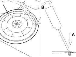
1. Use tool to release and remove the access cover to the fuel pump assembly.
Position the tool and apply leverage as indicated in the lever to prevent the cover tab deforming.
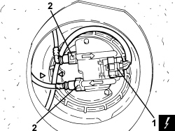
1. Disconnect the electrical connection from the submerged pump assembly complete with level gauge.
| Description | Connector | |
|---|---|---|
| 1 | Fuel pump and level gauge | See N040 FUEL PUMP AND LEVEL GAUGE |
2. Disconnect the rapid connectors for the fuel supply and return pipes, submereged pump assembly side complete with level gauge.
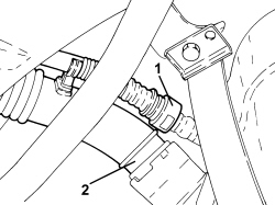
1. Disconnect the rapid connector for the breather pipe, fuel tank side.
2. Disconnect the rapid connector for the fuel filler pipe, fuel tank side.
1. Position a hydraulic jack with a suitable support under the fuel tank.
2. Undo the bolts (2a) and remove the fuel tank support belts (2b).
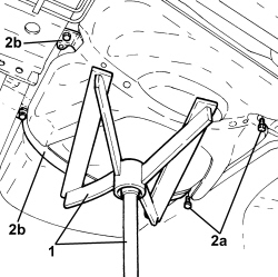
1. Lower the hydraulic jack slowly and remove the fuel tank.
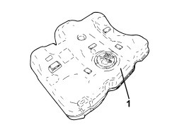
Refitting
- Place the fuel tank back in its housing using the hydraulic jack.
- Place the fuel tank support belts back in their housings and secure them tightening the bolts to the recommended torque.
| Component | Fastening | dia | Value (daNm) | Validity |
|---|---|---|---|---|
| Fuel tank | Bolt | M8 | (bodyshell side) 3.2 - 3.9 |
- Remove the hydraulic jack with a suitable support under the fuel tank.
- Connect the rapid connector for the fuel filler pipe, fuel tank side.
- Connect the rapid connector for the breather pipe, fuel tank side.
- Connect the rapid connectors for the fuel supply and return pipes, submereged pump assembly side complete with level gauge.
- Connect the electrical connection to the submerged pump assembly complete with level gauge.
- Place the access cover to the submerged pump assembly complete with level gauge back in its housing and secure it using the bolts.
Op. 7050A20 ONE-PIECE REAR SEAT CUSHION - R.R.
- Connect the negative battery terminal.
- Remove the vehicle from the lift.
Parts & tools for this job For 2005 Fiat Croma
- PARTEngine gasket setSearch: Fiat Croma 2005 engine gasket set
- TOOLTorque wrenchSearch: 3/8 inch torque wrench
- TOOLFeeler gauge setSearch: feeler gauge set
Links open Amazon search results in a new tab. As an Amazon Associate I earn from qualifying purchases.