
Air intake circuit (page 3 of 4)
- Make
- Fiat
- Model
- Scudo Factory Service Manual
- Year
- 1996–2006
- Section
- Fuel system (1581 SPI Monomotronic)
The adjustment of the idle speed is carried out automatically by the electronic control unit by means of a 12 V direct current electric motor which, using a suitable reduction system, acts directly on the butterfly valve operating linkage.
Incorporated in the butterfly opening motor there is a micro-switch, which is closed with the accelerator pedal in the rest position (released).
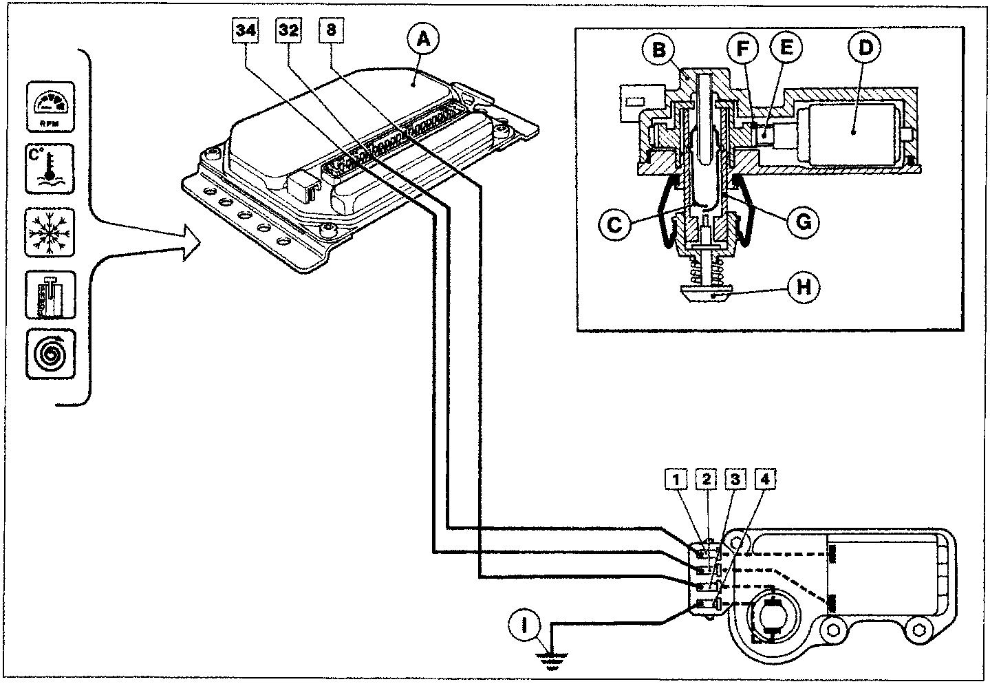
The restoring of the engine idle adjustment function after a cut-off stage is managed by the control unit (A) mainly in relation to the engine speed and the temperature of the engine coolant and, secondly, in relation to other parameters, namely: the engine during starting or warming up, the switching on of the air conditioning and the position of the selector lever if there is automatic transmission.
The function of controlling the idle is activated by the closing of the contact (C) which connects terminal 8 for the control unit to earth by means of terminals 3 and 4 for the motor (B) connector in point (I) on a special bracket under the starter motor.
When it is necessary, the control unit supplies the adjustment motor (D) via terminals 32 and 34 so that on opening or closing the butterfly valve the idle speed is corrected.
An electronic switch inside the control unit suitably reverses the polarities at the motor so that the two directions of rotation are obtained (clockwise and anti-clockwise).
The supply of the motor (D) causes the rotation of the reduction unit made up of a worm screw (E) and a helical wheel (F).
Inside the helical wheel there is a female screw on which the micro-switch (G) casing winds/unwinds so that it can extend/retract in relation to the direction of rotation of the actual wheel.
Parts & tools for this job For 1996 Fiat Scudo
- TOOLDigital multimeterSearch: automotive digital multimeter
- PARTAssorted fuse kitSearch: car fuse assortment kit
- TOOLWire crimper and connector kitSearch: wire crimper connector kit
Links open Amazon search results in a new tab. As an Amazon Associate I earn from qualifying purchases.