
h. Active diagnosis (page 2 of 3)
- Make
- Fiat
- Model
- Scudo Factory Service Manual
- Year
- 1996–2006
- Section
- Fuel system (1581 SPI Monomotronic)
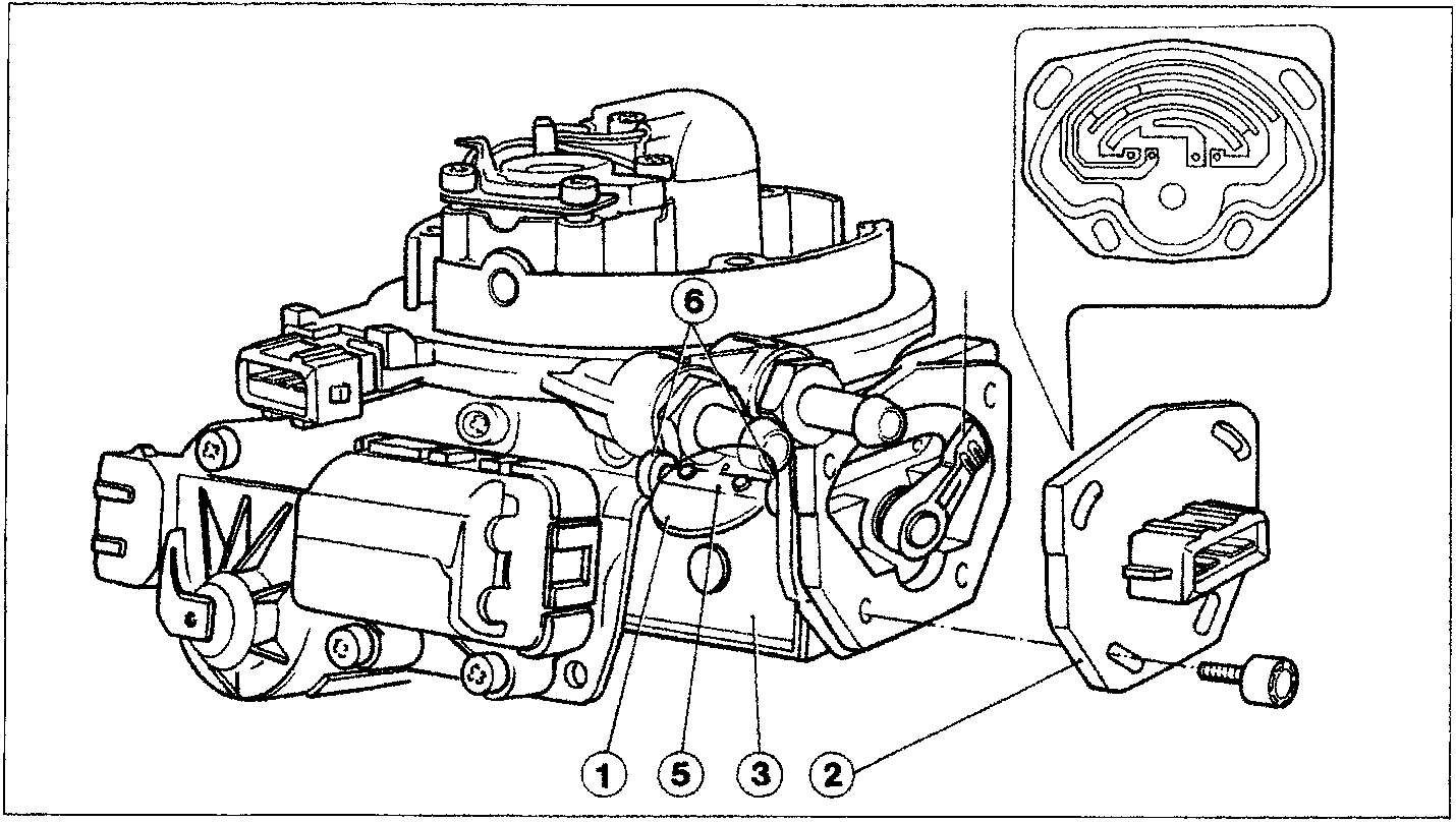
The butterfly (1) angle (α) position signal plays a fundamental role in determining the basic injection times.
This signal is detected by a twin track potentiometer (2) fitted on the butterfly casing (3) by means of a rotor arm with two twin combs (4) fixed to the butterfly valve shaft (5).
To prevent sticking or errors in detecting the angle α, the butterfly shaft is fitted on two ball bearings (6).
The potentiometer (2) is already adjusted in relation to the butterfly casing when it is fitted in the factory and should not therefore be removed for any reason; if there is a problem the complete butterfly casing must be replaced.
The control unit (A - see diagram overleaf) supplies terminal 5 of the butterfly valve angular opening sensor (B) via terminal 25 with a reference voltage equal to around 5 V (constant).
From terminal 2 for the potentiometer a voltage signal measured at the first track (C) is sent to terminal 12 of the control unit; it is proportional to the positions assumed by the butterfly in the first 24° (0° ÷ 24°) opening.
Parts & tools for this job For 1996 Fiat Scudo
- PARTFuel filterSearch: Fiat Scudo 1996 fuel filter
- TOOLFuel pressure test kitSearch: fuel pressure test kit
- TOOLFuel line disconnect toolSearch: fuel line disconnect tool
Links open Amazon search results in a new tab. As an Amazon Associate I earn from qualifying purchases.