
h. Active diagnosis (page 3 of 3)
- Make
- Fiat
- Model
- Scudo Factory Service Manual
- Year
- 1996–2006
- Section
- Fuel system (1581 SPI Monomotronic)
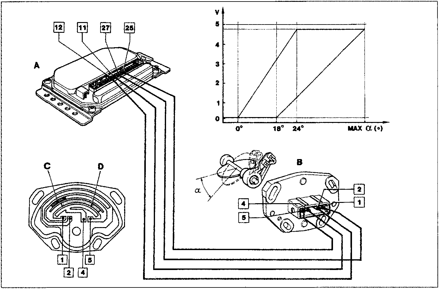
Consequently the signal assumes a value close to 0 Volt when the butterfly is completely closed and a value close to 5 Volt for an opening of 24° in relation to the rest position.
In the butterfly valve opening range from 0° - 24°, there are 10 reference points in the control unit map (α) which represent the same number of significant positions assumed by the butterfly valve. In this way the electronic control unit can recognize small angular variations in the range of about 2°25'.
This sensitivity allows the control unit to select the basic injection times in the special map during the more critical engine operating conditions such as during idling or partial load conditions, with greater precision.
Starting from a butterfly valve opening of 18° until it is completely open (about 90°), the signal supplied by terminal 4 of the potentiometer (B), i.e. that for the second track (D), comes into operation.
This signal, sent to terminal 11 of the control unit, relates to average and full load engine operating conditions.
The range for the second track is divided in the control unit map α with less resolution than for the first one, i.e. there are 5 points corresponding to angular variations of the butterfly valve of around 13°. Therefore, for the entire opening of the butterfly valve there are 15 significant points or openings (alfa) in the control unit which are recognized by means of the two potentiometer tracks.
With butterfly valve opening angles of between 18° and 24°, the simultaneous presence of voltage signals at terminals 2 and 4, for the first and second tracks, respectively, should satisfy a given ratio.
In the above mentioned conditions, the electronic control unit carries out a plausibility test to check the exact synchronization of the signals for the first track (C - minimum/partial load) and those for the second track (D - average load/full load).
Terminal 1 of the potentiometer is placed to earth in the control unit from terminal 27.
Parts & tools for this job For 1996 Fiat Scudo
- PARTFuel filterSearch: Fiat Scudo 1996 fuel filter
- TOOLFuel pressure test kitSearch: fuel pressure test kit
- TOOLFuel line disconnect toolSearch: fuel line disconnect tool
Links open Amazon search results in a new tab. As an Amazon Associate I earn from qualifying purchases.